
Bonneville V6-3800 38L (1991) Radiator Cooling Fan Motor Inspection
Wiring Diagram
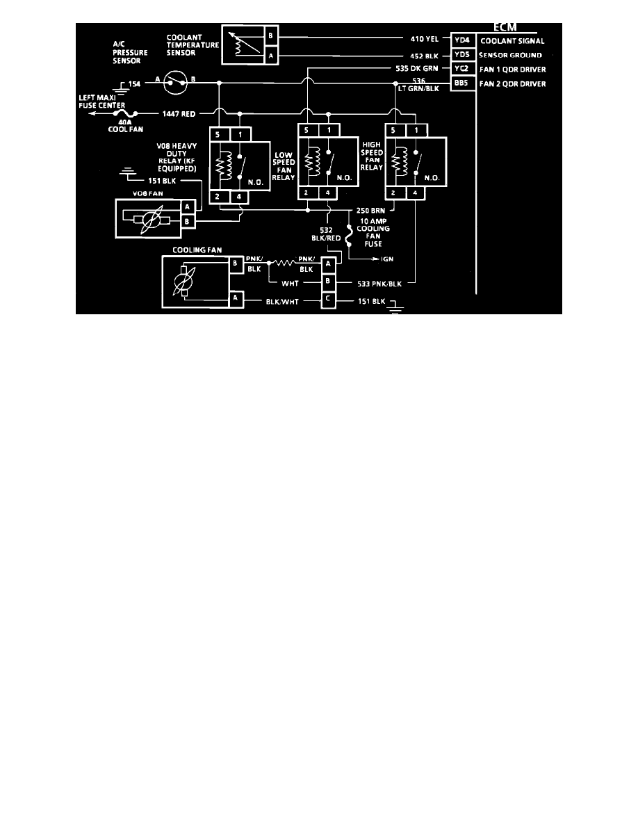
CIRCUIT DESCRIPTION:
Power for the fan motor comes through the fusible link to terminal "1" on all relays. The relays are energized when current flows to ground through the
ECM (quad-drivers).
Low Speed Relay - The ECM energizes the relay through terminal "YC2" when the coolant temperature reaches 101°C (214°F). As long as the ignition
remains in the "ON" position the coolant fan will continue to run until the coolant temperature falls below 99°C (210°F). The low speed fan will also run
any time the A/C is requested.
High Speed Relay - The high speed relay is energized by the ECM or the A/C pressure switch. If the A/C refrigerant pressure reaches 275 psi (1896 kPa)
or the coolant temperature reaches 108°C (226°F), the high speed fan relay is energized.
NOTE: Because of all the possible color code combinations used on electrical wiring diagrams, always refer to SCHEMATIC
DIAGRAMS/ELECTRICAL AND ELECTRONIC WIRING DIAGRAMS/ECM CONNECTOR IDENTIFICATION for correct color code
identification of circuit.
TEST DESCRIPTION: Numbers below refer to circled numbers on the diagnostic chart.
1.
Checks for battery voltage at relay harness connector.
2.
Jumpering terminals "1" to "4" bypasses the relay, which should cause the fan to run if fan motor and wiring to the motor are good.
3.
Grounding the test terminal should cause the ECM to ground CKT 535. At this point, the test light should light, if the ECM is good and CKT 535
isn't open.
4.
This checks for B+ and ground to the fan motor. A test light "ON" at this point indicates a faulty fan motor connection, motor connection, or
motor.
Part 4 of 4