
Bonneville V6-3800 3.8L Supercharged (1992)
ON-BOARD DIAGNOSTICS
The C68 Electronic Air Conditioning System is equipped with on-board diagnostics. The diagnostics feature displays fault codes, system data
parameters, and clears codes. It also commands some HVAC Programmer outputs. When a code is set, the temperature (external or set) will flash
during the first two minutes of operation. When in diagnostic mode, pressing AUTO at any time terminates the diagnostic mode. Refer to images for
procedures.
SCAN TOOL DIAGNOSTICS
The C68 Electronic Air Conditioning System has the ability to employ bi-directional scan tool diagnostics. The diagnostics feature displays fault
codes, system data parameters, and clears codes. It also commands some HVAC Programmer outputs and allows for snap shot and control head
monitoring. When a code is set, the temperature (external or set) will flash during the first two minutes of operation. The scan tool offers advantages
over the on-board diagnostics because the same faults that disable HVAC functions may disable the on-board diagnostics.
NOTE ON HISTORY CODES
Intermittent Faults
If the code set is a history code there is a good chance that the problem is intermittent or no longer exists. If the fault is intermittent, the diagnostics on
the following pages will not be effective in locating the fault. In most cases the fault must be present to locate the problem. Most intermittent problems
are caused by faulty electrical connections or wiring. When an intermittent fault is encountered check for:
^
Poor mating connector halves or terminals not fully seated in the connector body (backed out).
^
Improperly formed or damaged terminals. All connector terminals in a problem circuit should be carefully reformed to increase contact tension.
^
Poor terminal to wire connection. This requires removing the terminal from the connector body to inspect.
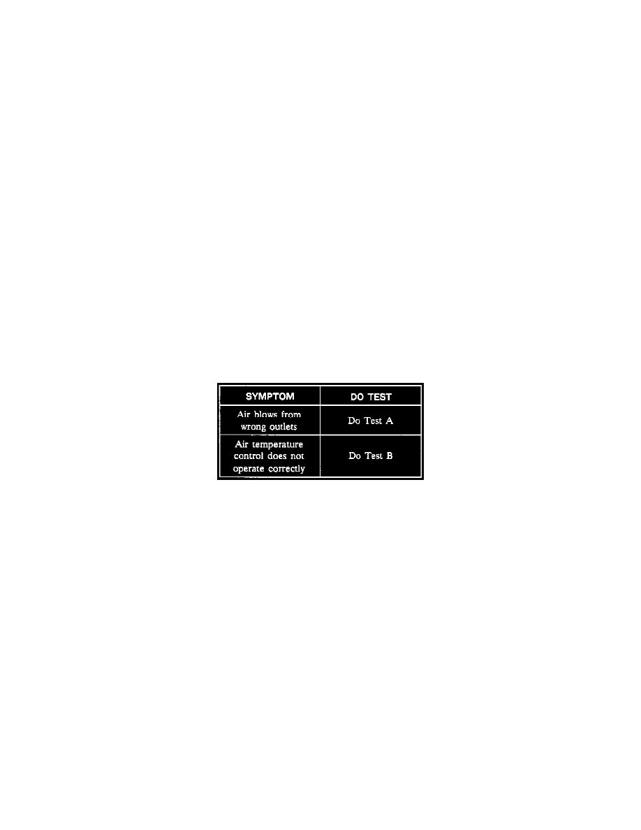
Manual Climate Controls
Symptom Table
^
Do the tests listed for your symptom in the Symptom Table (see image).
Automatic Climate Controls
Temperature control problems can result from refrigerant faults, electrical wiring or vacuum faults, mechanical faults (i.e. sticking valves) and/or
heater and A/C control assembly faults.
The automatic control air conditioning system can electronically identify several system faults. When the heater and A/C control assembly first detects
a fault, the set or outside temperature displayed flashes for approximately two minutes during each ignition cycle until the fault code is corrected or
cleared. If this occurs, the diagnostic mode can be entered and the display on the heater and A/C control assembly show a number which represents a
particular fault or circuit.
For diagnosis of refrigerant, vacuum, and mechanical faults, Refer to System Diagnosis / Procedures / Functional Test. See: Testing and Inspection
For additional A/C clutch diagnosis, Refer to Powertrain Management / Computers and Control Systems / System Diagnosis / Procedures. See:
Powertrain Management/Computers and Control Systems/Testing and Inspection
Often, a fault which is not identifiable by self-diagnostics can be located quickly by performing a thorough visual inspection of underhood
components, electrical harnesses, and vacuum hose connections.
If the programmer must be tested, be sure to keep it vertical to enable gravity to close off all vacuum supply through the solenoids not activated by the
heater and A/C control assembly.
Manual Climate Controls
If air flow does not come from the proper outlets under one or more operating modes, at least one of the air valves is not moving to the proper