
Bonneville V6-3800 3.8L VIN L SFI (1995)
Single Wire Feed Fusible Link
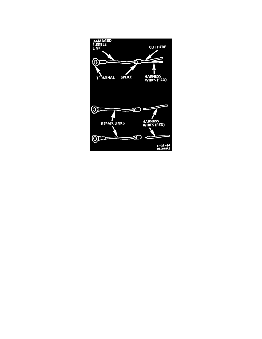
To replace a damaged fusible link, cut it off beyond the splice. Replace with a repair link. When connecting the repair link, strip wire and use
staking-type pliers to crimp the splice securely in two places. For more details on splicing procedures, refer to "Typical Electrical Repair Procedures."
Use crimp and seal splices whenever possible. See: Wire Repair Procedures/Typical Electrical Repair Procedures
Double Wire Feed Fusible Link
To replace a damaged fusible link which feeds two harness wires, cut them both off beyond the splice. Use two repair links, one spliced to each harness
wire.
General Information
The purpose of circuit protection is to protect the wiring assembly during normal and overload conditions. An overload is defined as a current
requirement that is higher than normal. This overload could be caused by a short circuit or system malfunction. The short circuit could be the result of a
pinched or cut wire or an internal device short circuit, such as an electronic module failure.
The circuit protection device is only applied to protect the wiring assembly, and not the electrical load at the end of the assembly. For example, if an
electronic component short circuits, the circuit protection device will assure a minimal amount of damage to the wiring assembly. However, it will not
necessarily prevent damage to the component.
There are three basic types of circuit protection devices: Circuit Breaker, Fuse and Fusible Link.
Diode Replacement
Many vehicle electrical systems use a diode to isolate circuits and protect the components from voltage spikes. When installing a new diode, use the
following procedure:
Step 1: Open the Harness
If the diode is taped to the harness, remove all of the tape.
Step 2: Remove inoperative Diode
Paying attention to current flow direction, remove inoperative diode from the harness with a suitable soldering tool. If the diode is located next to a
connector terminal, remove the terminal(s) from the connector to prevent damage from the soldering tool.
Step 3: Strip the Insulation
Carefully strip away a section of insulation next to the old soldered portion of the wire(s). Do not remove any more than is needed to attach the
new diode.