
Bonneville V6-3800 3.8L VIN L SFI (1995)
Engine Control Module: Specifications
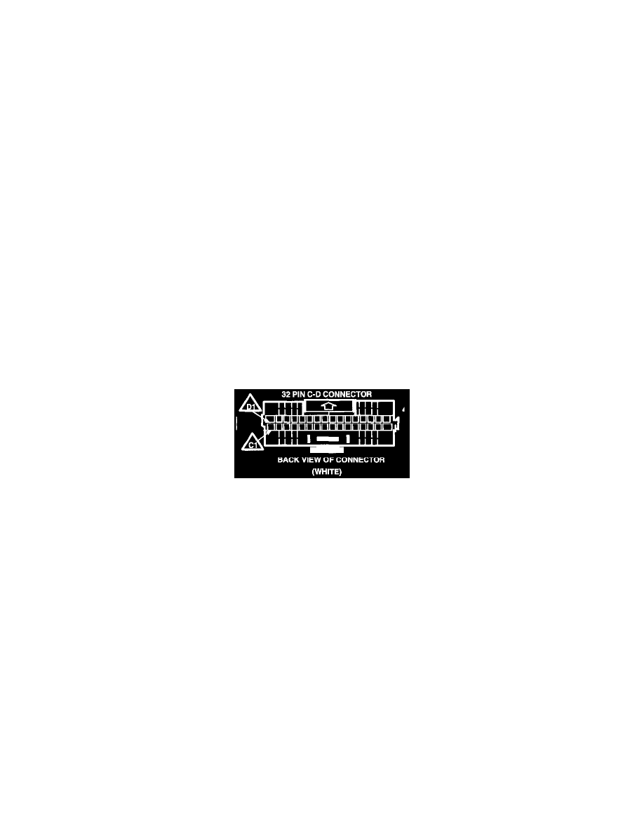
PCM Connector C-D (White)
POWERTRAIN CONTROL MODULE (PCM) VOLTAGE CHART
This PCM voltage chart is for use with a digital voltmeter to further aid in diagnosis. The voltages you get may vary due to low battery charge or
other reasons, but they should be very close. The B+ symbol indicates a nominal system voltage of 12-14 volts.
CONDITIONS FOR TESTING
^
Engine at operating temperature (upper radiator hose hot).
^
Engine idling in "Closed Loop" (for "Engine Run" column) in park or neutral.
^
Test terminal not grounded.
^
Scan tool not installed.
^
Accessories "OFF."
NOTE: Before checking voltages, be sure PCM and engine grounds are clean and tight.
CHART LEGEND
*
Less than 0.5 volts.
** If equipped.
***Foot off brake.
(1) B+ for 1st 2 seconds.
(2) Varies.
(3)Varies with temperature.
WHITE 32 PIN CONNECTOR
32 Pin C-D Connector (WHITE)