
Firebird V6-3.8L VIN K (1995)
Blower Motor: Initial Inspection and Diagnostic Overview
Heater
^
For Diagnosis "HVAC Blower control". See:
Circuit Operation
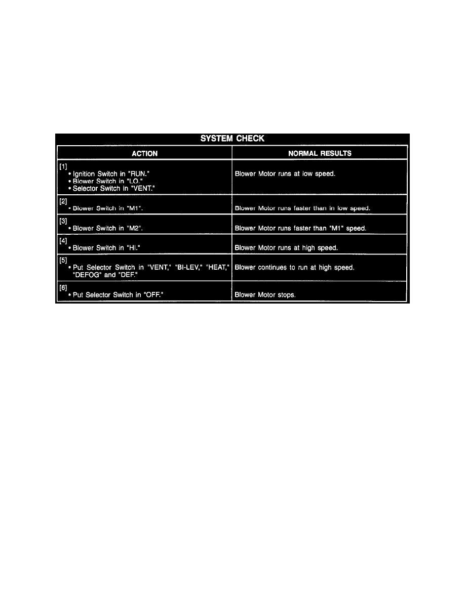
With the Ignition Switch in "RUN," battery voltage is applied to the Selector Switch. The Selector Switch applies power to the Blower Switch in all
modes but I/0 felt With the Blower Switch set to "LO," battery voltage is applied to the Blower Motor through the Blower Resistor and the normally
closed contacts of the High Blower Relay. The Blower Motor has at low speed. When the Blower Switch is in the "M1" or "M2" positions, the operation
is similar to the operation in "LO" except the resistance through the Blower Resistor is decreased, causing the Blower Motor to run faster in "M1" and
even faster in "M2". When "HI" blower speed is selected, the Blower Switch applies voltage to the High Blower Relay coil. The High Blower Relay is
energized, applying voltage from CKT 202 through the relay directly to the Blower Motor. The Blower Motor then runs at high speed.
System Check
System Diagnosis
^
Perform the System Check and refer to the Symptom Table for the appropriate diagnostic procedures. See: HVAC Blower Control/System
Check See: Symptom Related Diagnostic Procedures/Symptom Table
Troubleshooting Hints
Perform before beginning System Diagnosis
1. Check HVAC Fuse 3 for open. If open, check for short to ground through CKT 241.
2. Check Fusible Link A.
3. Check that G201 and G200 are clean and tight.
^
Check for a broken (or partially broken) wire inside of the insulation which could cause system malfunction but prove "GOOD" in a
continuity/voltage check with a system disconnected. These circuits may be intermittent or resistive when loaded, and if possible, should be
checked by monitoring for a voltage drop with the system operational (under load).
^
Check for proper installation of aftermarket electronic equipment which may affect the integrity of other systems (Refer to "Diagnostic
Aids/General Troubleshooting Procedures,"). See: Diagrams/Diagnostic Aids
^
Refer to System Diagnosis. See: HVAC Blower Control/System Diagnosis