
Firebird V6-3.8L VIN K (1995)
Oxygen Sensor: Description and Operation
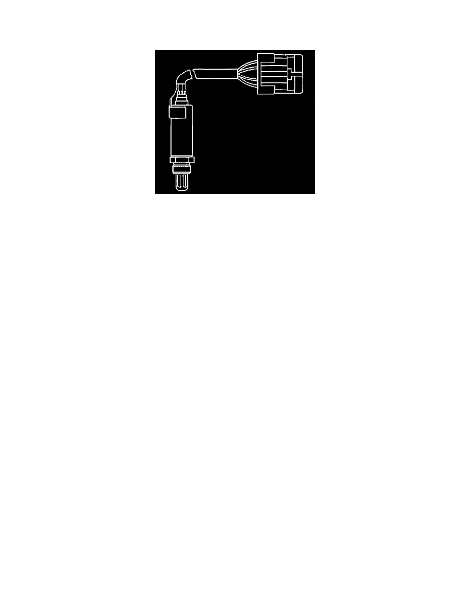
Fuel Control Oxygen Sensors
DESCRIPTION
The fuel control Heated Oxygen Sensors (Bank 1 HO2S 1 and Bank 2 HO2S 1) are mounted in the exhaust manifolds where they can monitor the
oxygen content of the exhaust gas stream. The oxygen present in the exhaust gas reacts with the sensor to produce a voltage output. This voltage
should constantly fluctuate from approximately 100 mV (high oxygen content - lean mixture) to 9OO mV (low oxygen content - rich mixture). The
heated oxygen sensor voltage can be monitored with a scan tool. By monitoring the voltage output of the oxygen sensor, the PCM calculates what
fuel mixture command to give to the injectors (lean mixture-low HO2S voltage = rich command, rich mixture-high HO2S voltage = lean
command).
The Bank 1 HO2S 1 circuit, if open, should set a DTC P0134 and the scan tool will display a constant voltage between 400 - 500 mV. A constant
voltage below 3OO mV in the sensor circuit (circuit grounded) should set DTC P0131, while a constant voltage above 8OO mV in the circuit
should set DTC P0132. Similarly, faults in the Bank 2 HO2S signal circuit will cause DTC P0154 (open circuit), DTC P0151 (grounded circuit),
or DTC P0152 (signal voltage high) to set. A fault in the Bank 1 HO2S 1 heater circuit should cause DTC P0135 to set. A fault in the Bank 2
HO2S 1 heater circuit should cause DTC P0155 to set. The PCM can also detect HO2S response problems. If the response time of an HO2S is
determined to be too slow, the PCM will store a DTC that indicates degraded HO2S performance.