
Firebird V6-3.8L VIN K (1995)
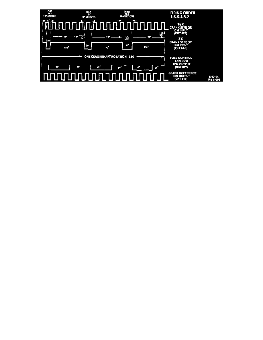
18X And 3X Crank Sensor Pulses And Crankshaft Reference Signals Sent To The PCM
OPERATION
The fuel control signal sent to the PCM by the ignition control module is an ON-OFF pulse occurring 3 times per crankshaft revolution. This is
neither the 3X nor the 18X crank sensor pulse, but both of these are required before the ignition control module will generate the fuel control
signal.
The ignition control module generates the fuel control signal by an internal "divide-by-6" circuit. This divider circuit divides the 18X crankshaft
position sensor pulses by 6. The divider circuit is enabled, or ready to begin dividing, only after it receives a 3X crankshaft position sensor pulse.
After beginning, the divider circuit does not need the 3X pulses to continue operating. if either the 18X or 3X pulses are missing at start-up, the
divider will not generate a fuel control signal pulses (sent to the PCM), and no fuel injector pulses will occur.
^
Anytime the PCM does not apply 5 volts to the ignition control module "bypass" circuit, the ignition control module controls ignition by
triggering each of the three coils in the proper sequence at a pre-determined dwell, with spark advance fixed at 10 degrees BTDC. This is
called module mode ignition. The ignition control module provides proper ignition coil sequencing during both the module and IC modes.
^
PCM applies 5 volts to the ignition control module "bypass" circuit, signaling the module to allow the PCM to control the dwell and spark
timing.
This is IC mode ignition. During IC mode, the PCM compensates for all driving conditions. Again, the ignition control module is responsible for
proper ignition coil sequencing during both the module and IC modes.