
Firebird V6-3.8L VIN K (1995)
Transmission Range (TR) Pressure Switch Assembly Circuit Check (Part 2 Of 2)
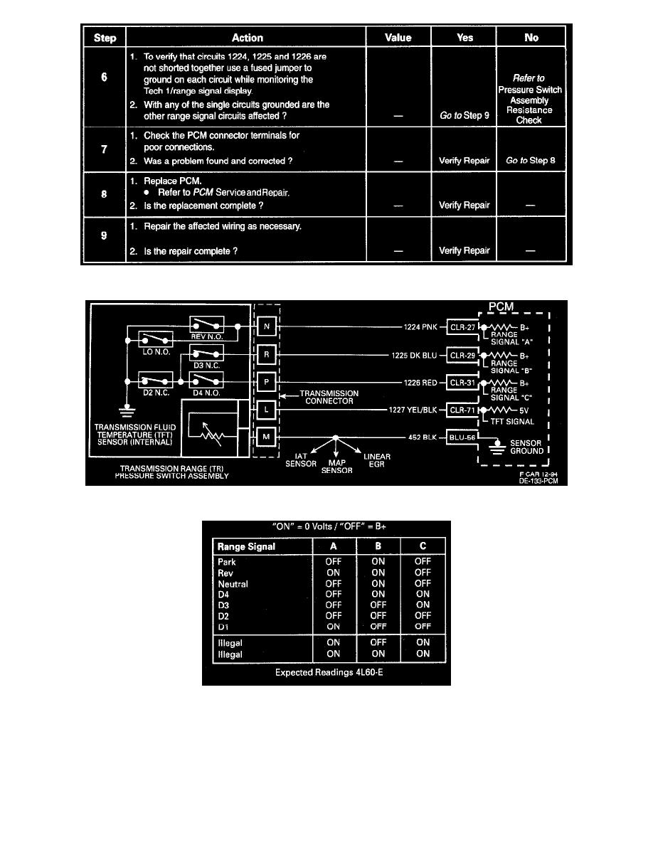
Transmission Fluid Temperature (TFT) Sensor Circuit
Valid Combination Chart
CIRCUIT DESCRIPTION
The Transmission Range (TR) switch assembly consists of five pressure switches (two normally closed and three normally open), and a Transmission
Fluid Temperature (TFT) sensor combined into one unit and mounted on the valve body. The Powertrain Control Module (PCM) supplies battery
voltage to each range signal. By grounding one or more of these circuits through various combinations of the pressure switches, the PCM detects what
manual valve position has been selected and compares the actual voltage combination of the switches to a TR combination chart stored in memory.
The TR assembly cannot distinguish between Park and Neutral because the monitored valve body pressures are identical in both cases. With ignition