
Firebird V8-305 5.0L (1982)
Compressor Clutch Diode HVAC: Technical Service Bulletins
Electrical Systems - Isolation Diode Replacement
Bulletin Number: 93-8-15
Reference Number: 178201R
Publish Date: 5/93
Subject:
INFORMATION CONCERNING REPLACEMENT OF ISOLATION DIODES
Models Affected:
1993 AND PRIOR YEARS ALL MODELS
THIS BULLETIN CANCELS AND REPLACES BULLETIN 92-8-7 ISSUED 12/91. PLEASE DISCARD BULLETIN 92-8-7.
Many of the electrical systems on our vehicles use a diode to isolate certain circuits and protect them from voltage spikes. Some of the circuits which
may use such a diode are listed below:
*
A/C Compressor Clutch
*
ABS/4WAL
NOTE:
The ABS diode on the Delco Moraine system is hidden inside of an electrical connector under the carpet at the right kick panel.
*
Wiper
*
Charging System (hidden in wire harness)
*
Parking Brake (vehicles with ABS)
*
Relays
*
Solenoids
*
Diesel Glow Plug Circuit
*
Day Time Running Lights
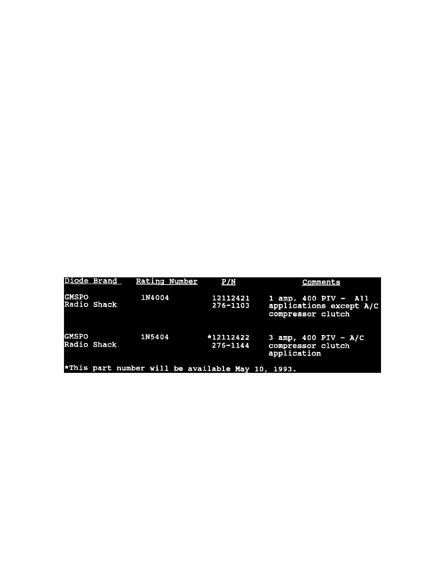
Obtaining replacement diodes can sometimes be a problem. A universal diode, that meets the specifications in the chart, may be used for the applications
listed above. Since certain diode applications have specific part numbers, always reference the applicable GM parts catalogue before installing one of the
universal diodes listed in this bulletin.
When installing the new diode, use the following procedures to obtain a lasting repair:
1.
If the diode is taped to the harness, remove all of the tape.
2.
Paying attention to current flow direction, remove inoperative diode from the harness with a suitable soldering tool. If the diode is located next to a
connector terminal, remove the terminal(s) from the connector to prevent damage from the soldering tool.
3.
Carefully strip away a section of insulation next to the old soldered portion of the wire(s). Do not remove any more than is needed to attach the
new diode.
4.
Check current flow direction of the new diode, being sure to install the diode with correct bias. Reference the appropriate service manual wiring
schematic to obtain the correct diode installation position. Reference Figure 1 for replacement diode symbols and current flow explanations.
Attach the new diode to the wire(s) using 60/40 rosin core solder. Use a heat sink (aluminum alligator clip) attached across the diode wire ends to
protect the diode from excess heat. Follow the manufacturer's instructions for the soldering equipment you are using.
5.
Install terminal(s) into the connector body if previously removed in step number 2.