Firebird V8-305 5.0L (1982)

Carrier Bearings: Adjustments
Exc. Borg Warner
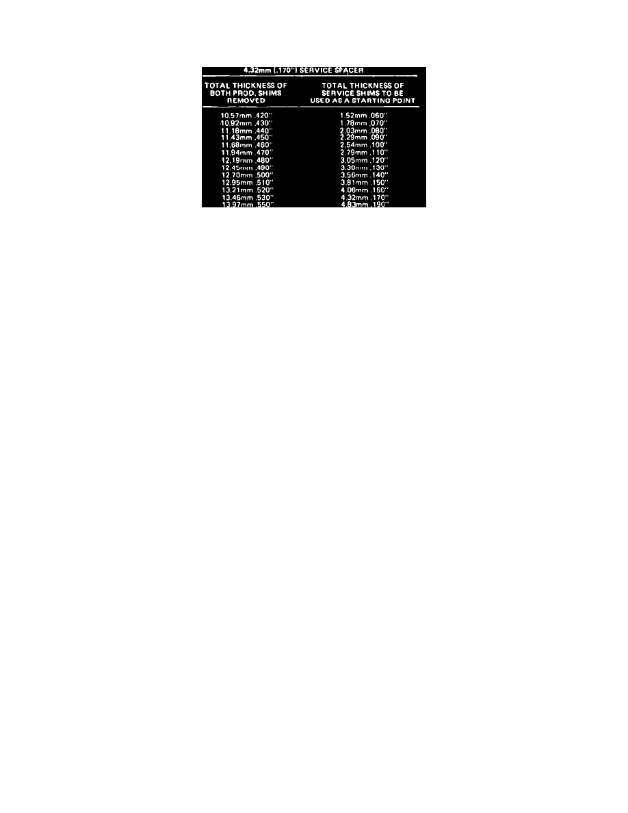
Fig. 18 Service shim thickness chart
EXC. CHEVETTE, 1000 & CORVETTE MODELS
On these models, side bearing preload should be set before pinion is installed. If pinion is installed, remove ring gear.
1.
Ensure that bearing bores in housing and bearing caps are clean and free from burrs.
2.
Measure production shims or service spacer and shim packs removed during disassembly to determine approximate thickness of shims needed for
installation. Do not reuse cast iron production shims as they may break during installation. If service spacers and shims were previously
installed, they can be reused.
3.
In addition to .170 inch service spacers for each side, refer to chart, Fig. 18, and select service shim thickness required based on measurements
made in step 2.
4.
Place outer races over side bearings, mount differential assembly in housing and insert service spacer between each bearing race and housing with
chamfered edge against housing.
5.
Install left bearing cap to retain case assembly and tighten bolts hand tight so that case can be moved while checking adjustments. A bearing cap
bolt can be installed in lower right bearing cap hole to prevent case from dropping while performing shim adjustments.
6.
Select one or two shims totaling thickness calculated in step 3 and insert shims between right bearing cap and service spacer.
7.
Insert progressively larger feeler gauges between shim and service spacer until noticeable increase in drag can be felt, pushing gauge down until it
contacts housing bore to obtain proper reading. Rotate case while inserting gauges to ensure even readings.
8.
The gauge used just before additional drag is felt is correct thickness to obtain ``zero preload.'' By starting with a thin gauge a sense of feel can be
obtained for the original light drag caused by the weight of the case, allowing the drag caused by the beginning of preload to be recognized. It will
be necessary to work case in and out and to the left in order to insert feeler gauges.
9.
When the proper gauge thickness has been determined to obtain zero preload, remove bearing cap, case assembly service spacers and shim pack.
10.
Select 2 service shims of approximate equal thickness whose total thickness is equal to the thickness of the shims installed in step 6 plus the
thickness of the feeler gauge used to obtain zero preload.
11.
Shims selected during this procedure allow differential assembly to be installed at zero preload, the equivalent of a ``slip-fit'' in case, during
backlash adjustment. Final preload is not added until backlash has been adjusted.
