
Firebird V8-350 5.7L VIN P SFI (1996)
Numbers below refer to the steps in the diagnostic table (see Attachments 9,10,11).
1.
This step uses the Radio to determine whether the fault is a short to ground or a short to B+. An inoperative Radio would indicate a short to ground
in circuit 75 or circuit 341 or an open RADIO Fuse 17 due to a short to ground in circuit 43. An operative Radio could indicate a short to B+ in
circuit 75, circuit 341, or circuit 43.
2.
This test determines if the Radio operates due to a short to B+ or a defective BCM.
4.
This step isolates the short to B+ to one side of RADIO Fuse 17.
5.
If the short to B+ is in circuit 43, this step determines if the short is caused by the Radio or Amplifier.
8.
If the vehicle is equipped with Steering Wheel Controls and the Radio and Amplifier are not the cause of the short to B+, this step determines if
the short is in the harness or the Steering Column.
11.
This step checks for a blown RADIO Fuse 17. A blown fuse would indicate a short to ground in circuit 43.
12.
If the short to ground is in circuit 43, this step determines if the short is caused by the Radio or Amplifier.
15.
If the vehicle is equipped with Steering Wheel Controls and the Radio and Amplifier are not the cause of the short to ground, this step determines
if the short is in the harness or the Steering Column.
19.
Knowing there is a short to B+ in circuit 75 (and therefore circuit 341), this test isolates the short to one side of connector C200 on vehicles
equipped with Power Windows.
20.
Knowing the short to B+ is on the C200C side of circuit 341, this test determines if the short is in the harness, the Power Window Control Module
or a Power Window Switch.
24.
Knowing the short to B+ is in the C200D side of circuit 341, this test determines if the short is caused by the Convertible Top Switch (if
equipped).
27.
Knowing the short to B+ is in the harness, this step isolates the fault to either circuit 75 or circuit 341.
29.
This step checks for an open in circuit 102.
32.
Knowing there is a short to ground in circuit 75 (and therefore circuit 341), this test Isolates the short to one side of connector C200 on vehicles
equipped with Power Windows.
33.
Knowing the short to ground is on the C200C side of circuit 341, this test determines if the short is in the harness, the Power Window Control
Module or a Power Window Switch.
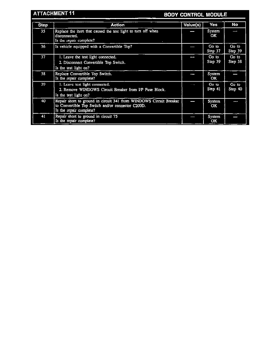
37.
Knowing the short to ground is in the C200D side of circuit 341, this test determines if the short is caused by the Convertible Top Switch (if