
Firebird V8-350 5.7L VIN P SFI (1996)
Body Control Module: Initial Inspection and Diagnostic Overview
Circuit Description
Voltage is applied at all times from POWER ACCY Fuse 7 and circuit 640 to the "SECURITY" Indicator lamp on the instrument Cluster. With the
Ignition Switch in the "BULB TEST" or "RUN" position, ground is applied by the BCM through circuit 728 to the "SECURITY" indicator lamp. The
"SECURITY" indicator lamp illuminates for approximately 5 seconds to verify circuit operation. The BCM also utilizes the "SECURITY" indicator
lamp to display DTC flash codes (as described earlier in this Section) by grounding circuit 728.
DTC Will Set When
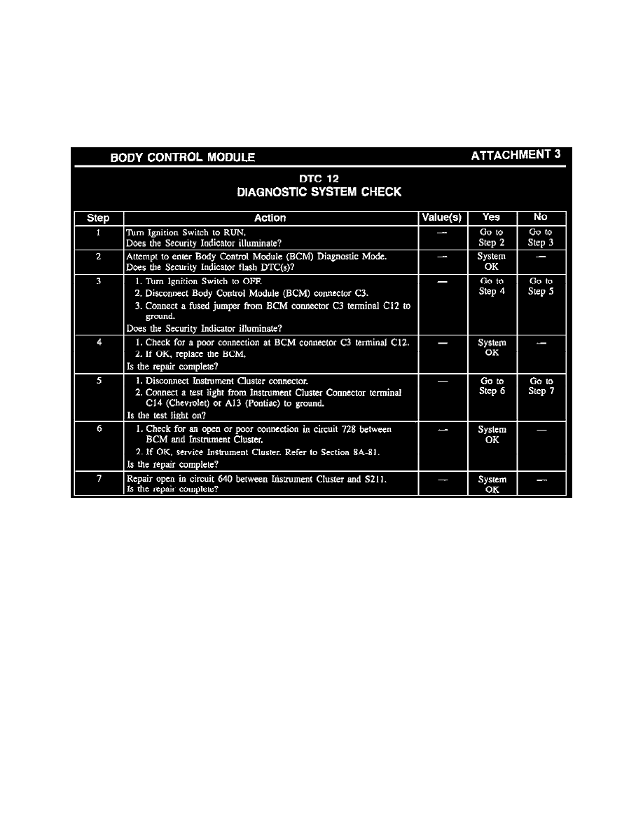
DTC 12 is always set and displayed when the BCM is in the Diagnostic Mode to indicate that the diagnostic function is in progress. if DTCs do not
display when the BCM is in the Diagnostic Mode, refer to the diagnostic chart (see Attachment 3).
Test Description
Numbers below refer to the steps in the diagnostic table (see Attachment 3).
1.
This step checks for "Security indicator lamp operation at "BULB TEST".
3.
If "Security" indicator does not illuminate, this step determines if the fault is in the BCM or the "Security" indicator circuit.
4.
This step checks for a poor connection at the BCM.
5.
This step checks for an open in circuit 640.
6.
This step checks for an open in circuit 728.