
Firebird V8-350 5.7L VIN P SFI (1996)
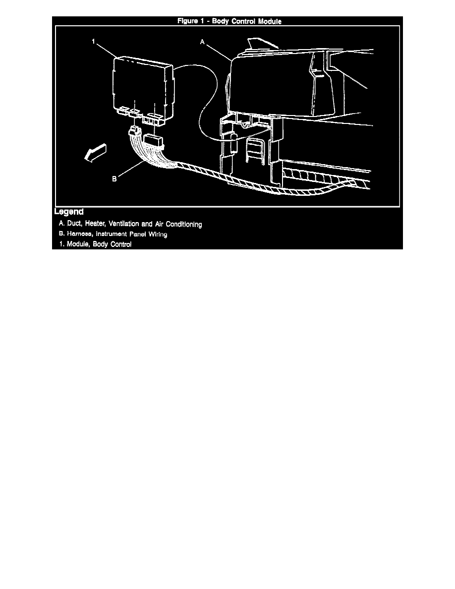
Figure 1
Important:
^
If BCM "C2" connector is removed first and reinstalled last, no BCM DTCs will set.
^
If BCM is being replaced (as opposed to being removed for access to other components), refer to "BCM Replacement" in Section 9D after new BCM
is installed in vehicle. This will enable the PASS-Key II® system portion of the BCM to properly code the new BCM to the present ignition key
being used.
^
A new BCM is programmed by the manufacturer in a "Factory Test" mode. This mode allows only limited functionality of the systems that are
controlled by the BCM. When a new BCM is installed, it is necessary to exit the factory test mode prior to returning the vehicle to the customer. To
restore normal operation to the BCM, cycle the Ignition Switch between the "RUN" and "OFF" positions 10 times or enter the Program Mode as
described in Section 9D.
Notice:
The BCM electrical connectors are designed with indexing tabs and slots, and will only fit one way. The connectors do not require excessive force
when installed correctly. Installing the connectors incorrectly can cause damage to the connectors, the BCM or other vehicle components or systems.
Remove or Disconnect
1.
Lower instrument panel insulator.
2.
Unsnap BCM from HVAC duct bracket. Lower BCM.
3.
Electrical connectors and remove BCM from vehicle.
Install or Connect
1.
Electrical connectors to BCM.
2.
Snap BCM to HVAC duct bracket.
3.
Lower instrument panel insulator.
Important:
G200 ground is the primary ground for the BCM and other electrical components. Failure of the BCM may occur if this ground is not clean and tight.