
Firebird V8-350 5.7L VIN P SFI (1996)
^
Wire insulation which is rubbed through, causing an intermittent short as the bare area touches other wiring or parts of the vehicle.
^
Wiring broken inside the insulation. This condition could cause a continuity check to show a good circuit, but if only 1 or 2 strands of a
multi-strand type wire are intact, resistance could be far too HI.
To avoid any of the above problems when making wiring or terminal repairs, always follow the instructions for wiring and terminal repair outlined under
the Repair Procedures.
Meter Connections
The previous diagnostic procedure was written to detect intermittents using the meter set to voltage. Whether using the current, voltage or resistance
setting to detect intermittents, it is necessary to connect the meter to the circuit.
Following are examples of the various methods of connecting the meter to the circuit to be checked:
^
Backprobe both ends of the connector and either hold the leads in place while manipulating the connector or tape the leads to the harness for
continuous monitoring while performing other operations or test driving. (Do not backprobe "Weather Pack(R)" type connectors.)
^
Disconnect the harness at both ends of the suspect circuit where it connects either to a component or to other harnesses.
^
Use Connector Test Adapter Kit J 35616-A to connect the meter to the circuit.
^
If the system being diagnosed has a specified Pinout or breakout box, it may be used to simplify connecting the meter to the circuit or for checking
multiple circuits quickly.
Aftermarket Accessories
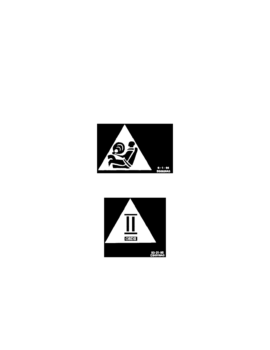
Do not tie aftermarket accessories into SIR circuits. All such circuits are indicated are indicated on circuit diagrams with the SIR symbol.
SIR Symbol
Do not tie aftermarket accessories into OBDII circuits. all such circuits are indicated on circuit diagrams with the OBDII symbol.
On Board Diagnostics II (OBDII) Symbol
Always check for aftermarket accessories (non-OEM) as the first step in diagnosing electrical problems. If the vehicle is so equipped, disconnect the
system to verify that these add-on accessories are not the cause of the problem.
Some possible causes of vehicle problems related to aftermarket accessories include:
1. Power feeds connected to points other than the Battery.
2. Antenna location.
3. Transceiver wiring located too close to vehicle electronic modules or wiring.
4. Poor shielding or poor connectors on antenna feed line.
Probing (Frontprobe & Backprobe)
After probing, when reconnecting connectors or replacing terminals, always be sure to reinstall Connector Position Assurance (CPA) and Terminal
Position Assurance (TPA).