
Firebird V8-350 5.7L VIN P SFI (1996)
NOTE: NEVER use force to remove a terminal from a connector.
Step 9:
Inspect terminal and connector for damage. Repair as necessary (refer to Terminal Repairs).
Step 10:
Reform lock tang and reseat terminal in connector body. Apply grease if connector was originally equipped with grease.
Step 11:
Install any CPAs or TPAs, close any secondary locks and join connector halves.
Weather Pack(R) Connectors
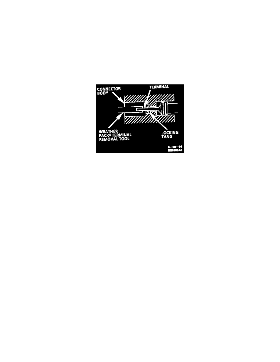
Typical Weather Pack(R) Connector And Terminal
Follow the steps below to repair Weather Pack(R) connectors.
Step 1:
Separate the connector halves.
Step 2:
Open secondary lock. A secondary lock aids in terminal retention and is usually molded to the connector.
Step 3:
Grasp the lead and push the terminal to the forward most position. Hold the lead at this position.
Step 4:
Insert the Weather Pack(R) terminal removal tool into the front (mating end) of the connector cavity until it rests on the cavity shoulder.
Step 5:
Gently pull on the lead to remove the terminal through the back of the connector.
NOTE: NEVER use force to remove a terminal from a connector.
Step 6:
Inspect the terminal and connector for damage. Repair as necessary (refer to Terminal Repair).
Step 7:
Re-form the lock tang and reseat terminal in connector body.
Step 8:
Close secondary locks and join connector halves.
Repairing Short Circuits Caused By Damaged Wire
^
Locate the damaged wire.
^
Find and correct the cause of the wire insulation damage.
^
For minor damage, tape over the wire. If damage is more extensive, replace the faulty segment of the wire (refer to the Splicing Instructions for
copper or shielded cable for the correct splicing procedure).
See: Wire Repair Procedures/Typical Electrical Repair Procedures/Splicing Copper Wire Using Splice Clips
See: Wire Repair Procedures/Typical Electrical Repair Procedures/Splicing Copper Wire Using Crimp and Seal Splice Sleeves