
Firebird V8-5.7L VIN G (2001)
^
Running out of fuel
^
Fuel-fouled spark plugs
^
A basic engine fault
Oxygen Sensor Diagnosis
Diagnose the Fuel Control Heated Oxygen Sensors for the following conditions:
^
The heater performance-the time to activity during a cold start
^
A slow response
^
The response time-the time to switch R/L or L/R
^
The inactive signal-the output should steady at a bias voltage of approximately 450 mV
^
A signal fixed high
^
A signal fixed low
Diagnose the Catalyst Monitor Heated Oxygen Sensors for the following functions:
^
The heater performance-the time to activity during a cold start
^
A signal fixed low during steady state conditions
^
An inactive sensor
PCM Function
The PCM supplies a buffered voltage to various sensors and switches. The PCM controls most components with electronic switches which complete a
ground circuit when the switches are turned ON.
PCM Service Precautions
The PCM is designed to withstand the normal current draws that are associated with vehicle operations. Avoid overloading any circuit. When you test for
opens or for shorts, do not ground any of the PCM circuits unless you are instructed. When you test for opens or for shorts, do not apply voltage to any
of the PCM circuits unless you are instructed. Test these circuits with a digital voltmeter only, while the PCM connectors remain connected.
System Status and Drive Cycle For Inspection/Maintenance
The System Status selection is included in the scan tool System Info menu.
Several states require that the I/M (OBD II system) pass on-board tests for the major diagnostics prior to having a vehicle emission inspection. This test
is also a requirement to renew the license plates in some areas.
Using a scan tool, the technician can observe the System Status of Complete or Not Complete in order to verify that the vehicle meets the criteria to
comply with local requirements. Using the System Status display, any of the following systems or combination of systems may be monitored for I/M
Readiness:
^
The catalyst
^
The EVAP system
^
The HO2S
^
The HO2S heater
^
The EGR system
^
The AIR system
IMPORTANT: The System Status display indicates only whether the test has been completed. The System Status display does not indicate whether the
test has passed. If a Failed Last Test indication is present for a DTC associated with one of the above systems, diagnosis and repair is necessary in order
to meet the I/M requirement. Verify that the vehicle passes all of the diagnostic tests associated with the displayed System Status prior to returning the
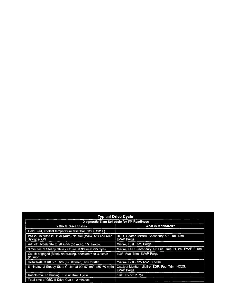
vehicle to the customer. Refer to the Typical Drive Cycle table to use as a guide to complete the I/M System Status tests. More than one drive cycle may
be necessary.
Typical Drive Cycle