
G5 L4-2.2L (2007)
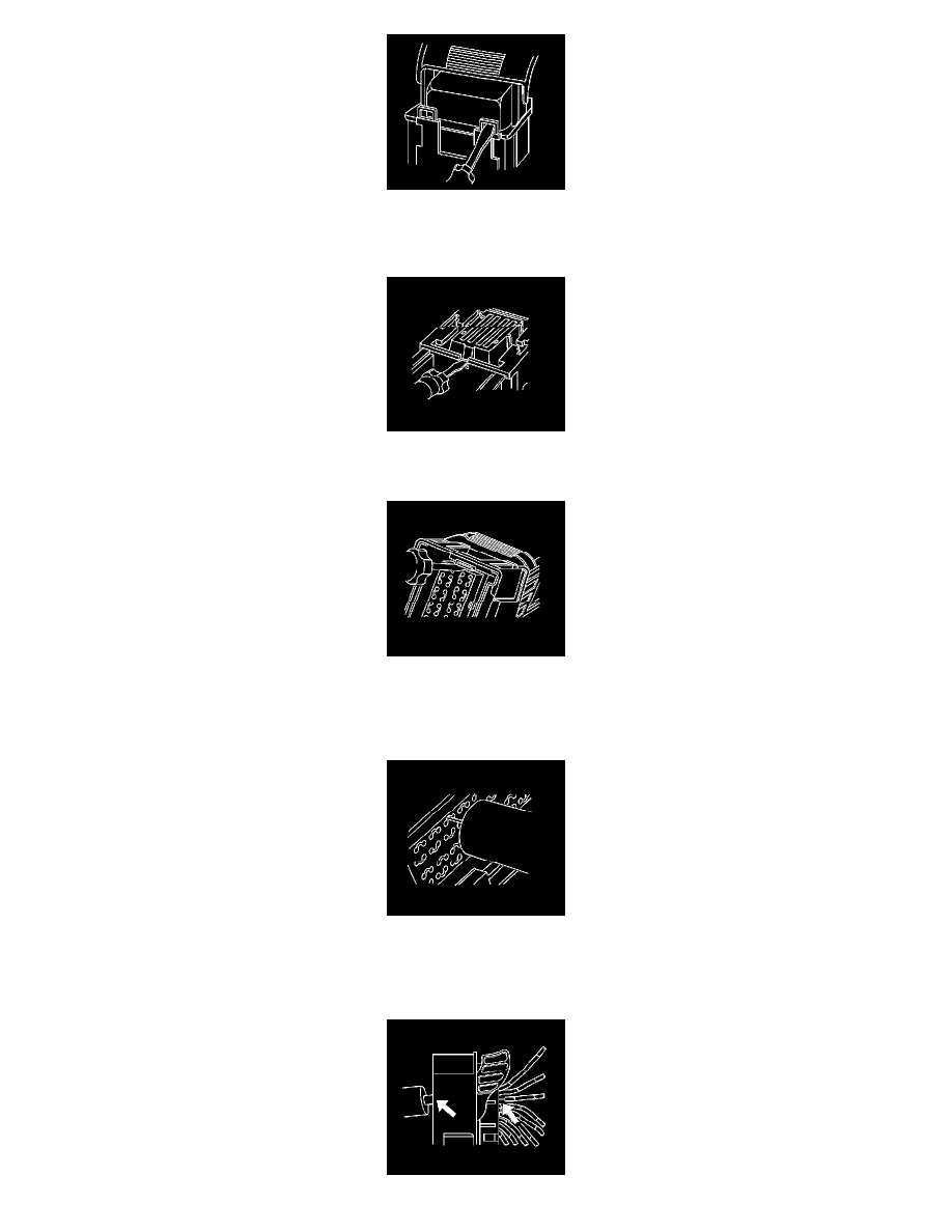
3. Locate the dress cover locking tabs at the front of the connector. Using a small flat-blade tool push down on one of the locking tabs and pull the
cover up until the dress cover releases. Repeat this procedure for the other locking tab.
4. Once the front 2 locks are unlocked, lift the front of the dress cover and pull it forward.
5. If the connector has a nose piece, use a small flat-blade tool to remove the nose piece by inserting the blade into the slot on the front of the
connector and prying up on the nose piece.
6. IMPORTANT: Always use care when removing a terminal position assurance (TPA) in order to avoid damaging it.
Remove the TPA by inserting a small flat-blade tool into the small slot on the TPA and pushing down until the TPA releases. Gently pry the TPA
out of the connector.
7. IMPORTANT: Be careful not to angle or rock the J 38125-21A tool when inserting it into the connector or the tool may break.
Insert the J 38125-21A (GM P/N 15381651-2) tool into the round canal between the terminals cavities at the front of the connector. See the release
tool cross reference in the Reference Guide of the Terminal Repair Kit to ensure that the correct release tool is used.