
G6 V6-3.5L (2009)
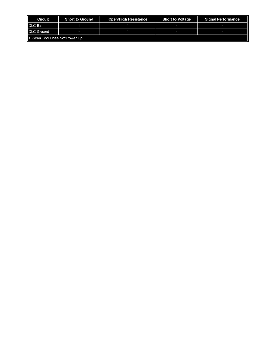
Circuit/System Description
The data link connector (DLC) is a standardized 16 cavity connector. Connector design and location is dictated by an industry wide standard, and is
required to provide the following:
*
Scan tool B+ voltage at terminal 16
*
Scan tool ground at terminal 4
*
Common ground at terminal 5
Diagnostic Aids
*
The scan tool will power up with the ignition OFF. Some modules however, will not communicate unless the ignition is ON and the power mode
master (PMM) module sends the appropriate power mode message.
*
If the B+ circuit, ground circuits, and connections of the DLC are functioning properly, the malfunction must be due to the scan tool/CANdi
module.
Reference Information
Schematic Reference
Data Communication Schematics (See: Diagrams/Electrical Diagrams)
Connector End View Reference
Component Connector End Views (See: Diagrams/Connector Views)
Description and Operation
Data Link Communications Description and Operation (See: Description and Operation)
Electrical Information Reference
*
Circuit Testing (See: Testing and Inspection/Component Tests and General Diagnostics)
*
Connector Repairs (See: Testing and Inspection/Component Tests and General Diagnostics)
*
Testing for Intermittent Conditions and Poor Connections (See: Testing and Inspection/Component Tests and General Diagnostics)
*
Wiring Repairs (See: Testing and Inspection/Component Tests and General Diagnostics)
Scan Tool Reference
Control Module References (See: Testing and Inspection/Programming and Relearning) for scan tool information.
Circuit/System Testing
1. Test for less than 2.0 ohms between the ground circuits terminal 4 of the DLC and ground, and terminal 5 of the DLC and ground.
‹› If greater than the specified range, test the ground circuit for an open/high resistance.
2. Ignition ON, verify a test lamp illuminates between the B+ circuit terminal 16 at the DLC and ground.
‹› If the test lamp does not illuminate, test the voltage supply circuit for a short to ground or an open/high resistance.
3. If all circuits test normal, refer to the scan tool/CANdi module user guide.
Repair Instructions
Perform the Diagnostic Repair Verification (See: Testing and Inspection/Diagnostic Trouble Code Tests and Associated Procedures/Verification Tests
and Procedures) after completing the repair.