
G6 V6-3.5L (2009)
cut positions 6, 8, and 10.
10. Check for correct loading by holding the tumblers (3) in position and fully inserting the matching key into the cylinder (1). All tumblers should be
flush with the outside diameter of the cylinder.
11. Lightly lubricate tumbler (3) surfaces using the lubrication provided.
12. With the matching key fully inserted into the coded cylinder, install the coded cylinder into the case (4).
13. Remove the matching key being careful to keep the coded cylinder (1) fully inserted into the case (4).
14. Insert one shutter spring (5) each into the 2 shutter spring holes located on the front face of the cylinder (1).
15. Install the shutter assembly (6) into the recessed area on the front face of the cylinder (1). Be sure that the ends of the pin on the shutter assembly
are positioned in the pin cavities located in the front face of the cylinder.
Note: Be careful not to scratch or dent the cosmetic surface of the cap or damage the lock cylinder in any way while staking the cap.
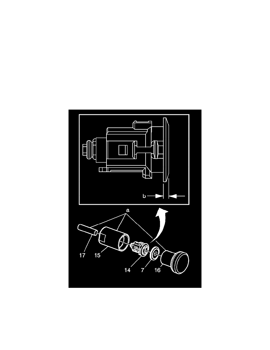
16. Stake the cap (7) onto the head of the case (4) by using the appropriate staking tool BO-48370 . Ensure proper orientation and set the cylinder
assembly (14), (which includes the case (4), coded cylinder (1), shutter springs (5), and shutter assembly (6)) and the cap (7) into the staking cup
(15) and clamp into vise. Remove any debris and install the cleaned staking ram (16) into staking cup (15) and with a dead blow hammer, hit the
staking ram (16) with moderate force 2 or 3 times. Check to determine if cap is securely staked to the cylinder assembly (14). Repeat previous step
until cap is securely staked to the cylinder assembly. Remove assembly from the staking cup (15). If necessary, insert the removal punch (17) into
the opposite end of the staking cup and tap lightly. Confirm that the shutter springs (5) push the shutter assembly (6) up against the inside surface
of the cap (7).
17. Install the gasket (8) over the end of the cylinder assembly and slide it all the way up the case (4) until it seats behind the cap (7).
18. Install the return spring (9) over the back end of the cylinder (1) with the straight hook facing the rear of the case (4). Engage the straight hook of
the return spring with the hook feature on the rear of the case.
19. Install the spacer (10) and lever (11) onto the end of the cylinder (1).
20. Install the retaining ring (12) in the groove at the end of the cylinder (1) to secure the lever (11) to the cylinder. Engage the bent hook of the return
spring (9) with the lever.
21. Install the theft deterrent switch (13) onto the end of the cylinder (1) and snap the switch legs onto the case (4). Be sure the theft deterrent switch is
engaged with the end of the cylinder and is securely attached to the case.
22. Check the operation of the lock assembly. The return spring (9) should provide a counterclockwise snap back.