
G6 V6-3.5L (2009)
-
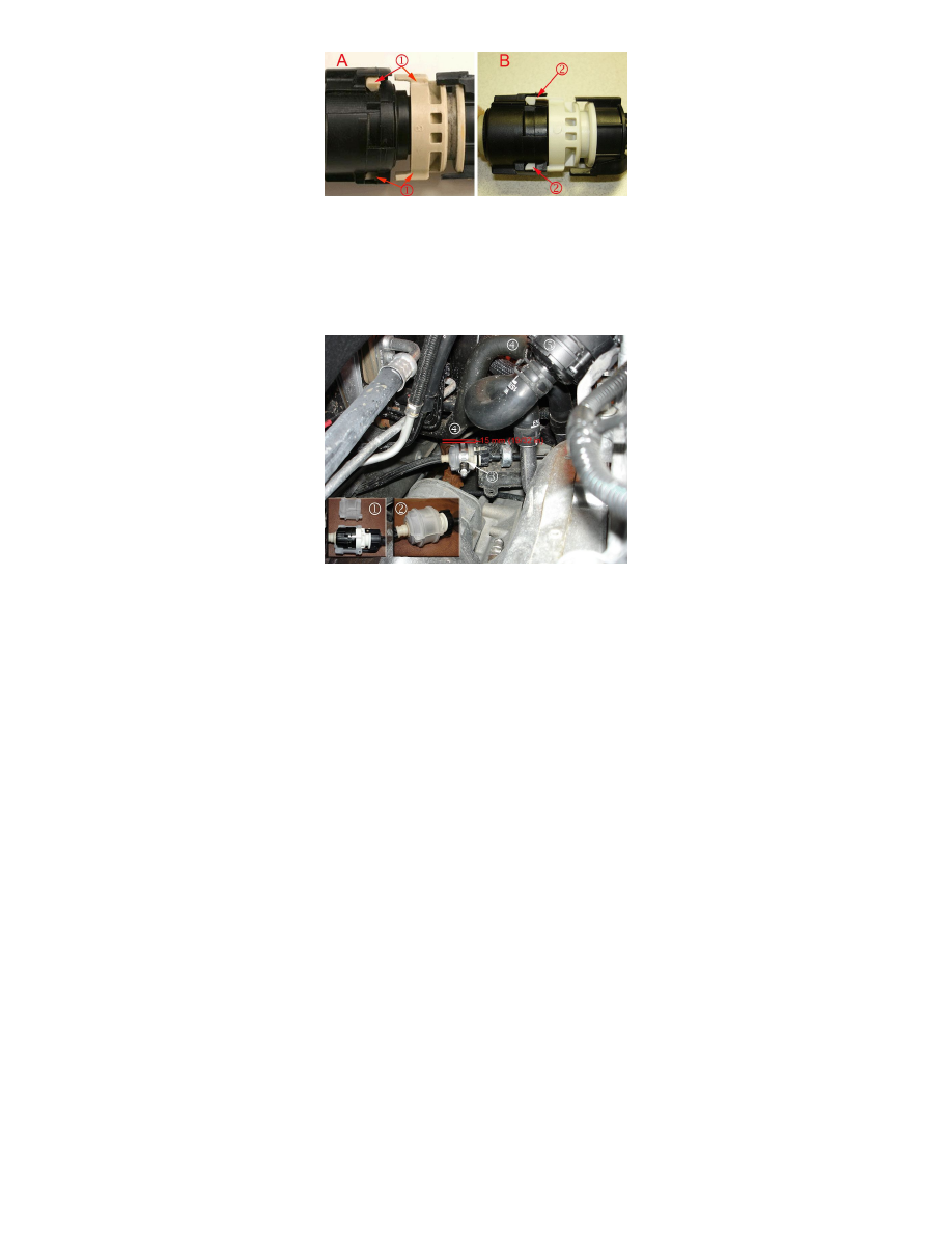
If the transmission shift cable locking tabs (1) are fractured and separated (A), remove the transmission shift cable and replace it with a new
one. Refer to Floor Shift Control Cable Replacement or Range Selector Lever Cable Replacement in SI. No further repairs are required after
replacing the transmission shift cable. Submit warranty claim
-
If the transmission shift cable locking tabs (2) are NOT fractured and separated (B), install the transmission shift cable kit. Proceed to Step 3.
Hybrid Vehicle Shown - Combustion Engine Vehicle is Similar
Clam Shell in Two Pieces
Clam Shell Around Shift Cable Locking Tabs
Clamp on Clam Shell
Inlet Coolant Hose and
Heater Cooler Pump
3. Install the clam shell (1) (2) over the shifter cable locking tabs.
4. Install the service clamp over the clam shell (3). Position the clamp fastener head away from the inlet coolant hose (4). Tighten the clamp to 4
Nm(35 lb in).
5. Ensure that there is 15 mm (19/32 in) of clearance between the inlet coolant hose (4) and the clam shell (3). On hybrid equipped vehicles, it may
be necessary to reposition the inlet coolant hose (4) to achieve the required 15 mm (19/32 in) of clearance. To reposition the inlet coolant hose
(4) on hybrid equipped vehicles, locate the heater cooler pump (5) and perform Steps 5.1-5.4.
Caution
Do not kink or damage the inlet coolant hose (4) when repositioning the hose to obtain the 15 mm (19/32 in) clearance. To avoid damaging the
hose clamp, use J-38185 or equivalent hose clamp pliers to loosen the hose clamp.
1. Using J-38185 or equivalent hose clamp pliers, loosen the inlet coolant hose (4) connected to the heater cooler pump (5). Note the location of
the clamp on the inlet coolant hose (4).
2. Rotate the inlet coolant hose (4) clockwise until 15 mm (19/32 in) of clearance between the inlet coolant hose (4) and clam shell (3) is
achieved.
3. Ensure that the inlet coolant hose clamp is secure on the inlet coolant hose (4) in the production location.
4. Install the generator control module cover. Refer to Generator Control Module Cover Replacement in SI.
6. Determine if additional repairs are required.