
G6 V6-3.9L (2009)
Brake Rotor/Disc: Testing and Inspection
Brake Rotor Assembled Lateral Runout Correction - Correction Plates
Brake Rotor Assembled Lateral Runout Correction - Correction Plates
Special Tools
*
J 39544-KIT Complete Torque Socket Set-10 Pieces, or equivalent
*
J 45101-100 Conical Brake Rotor Washers
Warning: Refer to Brake Dust Warning (See: Service Precautions/Technician Safety Information/Brake Dust Warning).
Note:
*
Brake rotor thickness variation MUST be checked BEFORE checking for assembled lateral runout (LRO). Thickness variation exceeding the
maximum acceptable level can cause brake pulsation. Refer to Brake Rotor Thickness Variation Measurement (See: Brake Rotor Thickness
Variation Measurement).
*
Brake rotor assembled LRO exceeding the maximum allowable specification can cause thickness variation to develop in the brake rotor over time,
usually between 4 800-11 300 km (3,000-7,000 mi). Refer to Brake Rotor Assembled Lateral Runout Measurement (See: Brake Rotor Assembled
Lateral Runout Measurement).
1. Rotate the brake rotor to position the high spot, identified and marked during the brake rotor assembled LRO measurement procedure, to face
upward.
2. Remove the J 45101-100 and the lug nuts that were installed during the assembled LRO measurement procedure and/or the indexing correction
procedure.
3. Inspect the mounting surface of the hub/axle flange and the brake rotor to ensure that there are no foreign particles or debris remaining.
4. Select the correction plate, following the manufacturer's instructions, which has a specification closest to the assembled LRO measurement.
For example: If the assembled LRO measurement was 0.076 mm (0.003 in), the 0.076 mm (0.003 in) correction plate would be used. If the
measurement was 0.127 mm (0.005 in), the 0.152 mm (0.006 in) correction plate would be used.
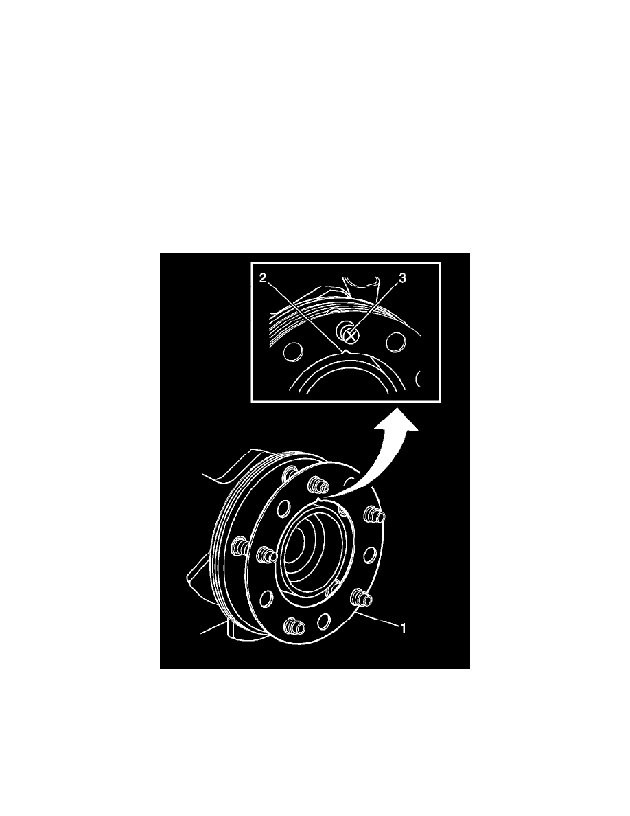
5. Determine the positioning for the correction plate (1) using the high spot mark (3) made during the brake rotor assembled LRO measurement