
G8 V6-3.6L (2008)
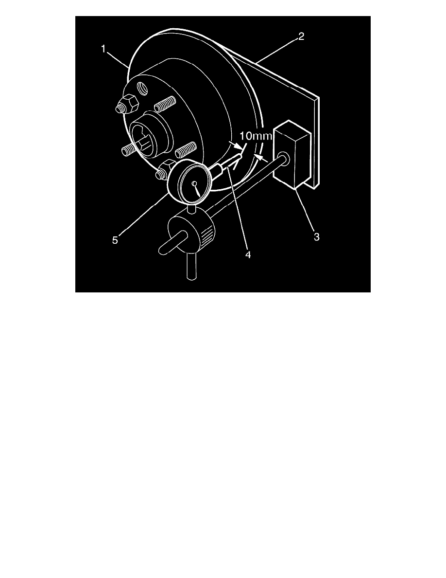
5. Set up a dial indicator (1) on a magnetic mounting base (2) and attach to the dial indicator plate (3).
6. Position the pointer (4) about 10 mm (3/8 in), from the outer edge of the brake disc (5).
Important: The number of divisions between the points of minimum and maximum runout on the dial indicator is the total indicated
runout.
7. Carefully rotate the brake disc and note the points of minimum and maximum runout on the dial indicator.
Important: If the lowest assembled brake disc runout achieved is more than 0.05 mm (50 micron), then the trunnion hub runout should
be inspected as detailed in the Hub Runout procedure.
8. Record this figure together with the number on the brake disc aligned with the chalk-marked stud.
9. Remove and reinstall brake disc with hole number 2 over the marked stud and repeat Step 4. This procedure is to be repeated for all 5 hole
positions.
Maximum assembled brake disc and hub runout at brake disc outer diameter - rear brake disc: 0.05 mm
10. Mount the brake disc to the hub in the stud position which recorded the least amount of runout.
Hub Runout Inspection - Front
Caution: Refer to Safety Glasses Caution (See: Service Precautions/Technician Safety Information/Safety Glasses Warning) .
Caution: Refer to Vehicle Lifting Caution (See: Maintenance/Vehicle Lifting/Service Precautions) .
Caution: Refer to Brake Dust Caution (See: Service Precautions/Technician Safety Information/Brake Dust Caution) .
1. Clean the front hub face with fine emery paper.