
Grand AM L4-144 2.4L DOHC VIN T SFI (1997)
Engine Control Module: Service and Repair
PCM/EEPROM Replacement/Programming
*** This article includes updates made by Technical Service Bulletin # 61-65-59, dated December, 1996 ***
PCM Installation
Re-Programming Precautions
A faulty PCM will be determined in the diagnostic tables. Before replacing the PCM, a re-programming procedure should not be attempted unless
instructed. If the re-programming is unsuccessful a DTC P0602 will set.
Malfunctioning EEPROM
An incorrect or malfunctioning EEPROM, which is part of the PCM, will set a DTC P0601. Before replacing the PCM, a re-programming procedure
should not be attempted unless instructed. If the re-programming is unsuccessful a DTC P0602 will set.
Notice:
^
In order to prevent internal damage to the PCM, the ignition must be OFF when disconnecting or reconnecting the PCM connector.
^
Service of the PCM should normally consist of either replacement of the PCM, EEPROM re-programming.
^
If the diagnostic procedures call for the PCM to be replaced, the PCM should be checked first to see if it is the correct part. DTC P0601
indicates the EEPROM programming has malfunctioned. When DTC P0601 is obtained, re-program the EEPROM.
^
The ignition should be OFF for at least 10 seconds before disconnecting power to the PCM so the IAC valve has time to move to the engine
OFF position.
Removal Procedure
Important: To prevent internal PCM damage, the ignition must be OFF when disconnecting or reconnecting power to PCM (for example, battery
cable, PCM pigtail, PCM fuse, jumper cables, etc.). The ignition should be OFF for at least 10 seconds before disconnecting power to the PCM so
the IAC valve has time to move to the engine OFF position.
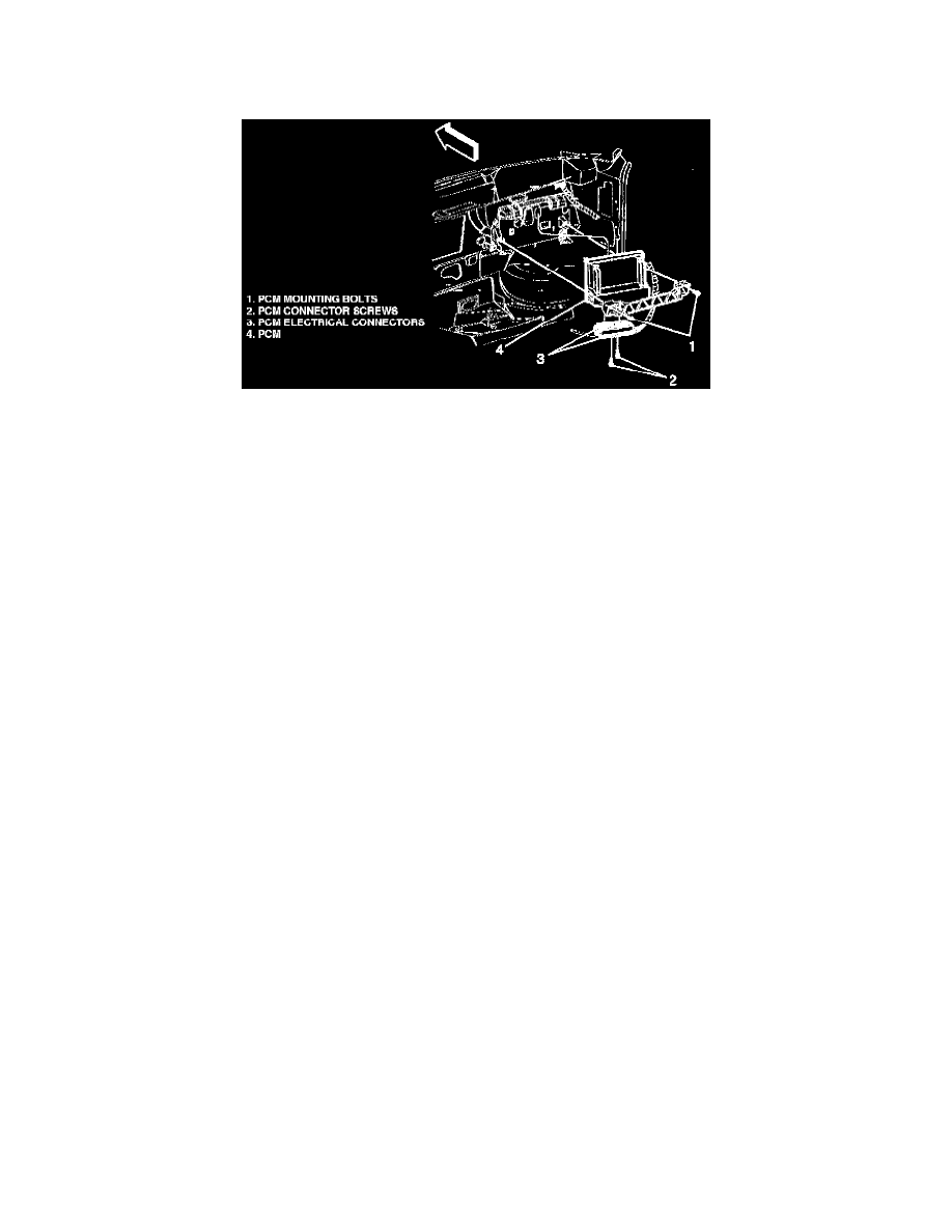
Notice: Numbers in text correspond to numbered components in image.
1. Disconnect the negative battery cable.
2. Remove the RH hush panel.
3. Loosen the PCM connector screws (2).
Notice: In order to prevent possible electrostatic discharge damage to the PCM, do not touch the connector pins or soldered components on the
circuit board. Do not remove the integrated circuit boards from the carrier.
4. Disconnect the PCM electrical connectors (3).
Important: PCM removal is eased when the glove box door is opened.