
Grand AM V6-3.4L VIN E (2001)
6.2.
Rotate the rotor and locate the point with the highest dial indicator reading (rotor "high spot").
6.3.
Note the amount and location of the "high spot" on the rotor and mark the closest wheel stud relative to this location.
7.
Select the appropriate "Brake Align(R) Correction Plate" required to compensate for the lateral run-out from the plates listed in the chart below.
Verify that the plate selected corrects the run-out specification to within .040 mm (.0015 in) or less.
8.
Remove the wheel nuts, conical washers and rotor.
Important:
Never attempt to stack two or more Correction Plates together on one hub. Never attempt to re-use a previously installed Correction Plate.
9.
Following the Brake Align(R) procedures and diagram, install the Correction Plate onto the vehicle between the hub and rotor. The V-notch in the
Correction Plate is to be installed and aligned with the noted location of the "high spot" on the vehicle hub and marked wheel stud.
10.
Install the rotor onto the vehicle with the Correction Plate placed between the hub and the rotor. Be sure to install the rotor onto the hub in the
same location as identified in Step 6.3.
11.
Re-install the calipers and wheels.
Important
It is critical to follow the procedure below for torquing the wheels. Brake rotors may be distorted if the wheel nuts are tightened with an impact
wrench or if this procedure is not followed exactly.
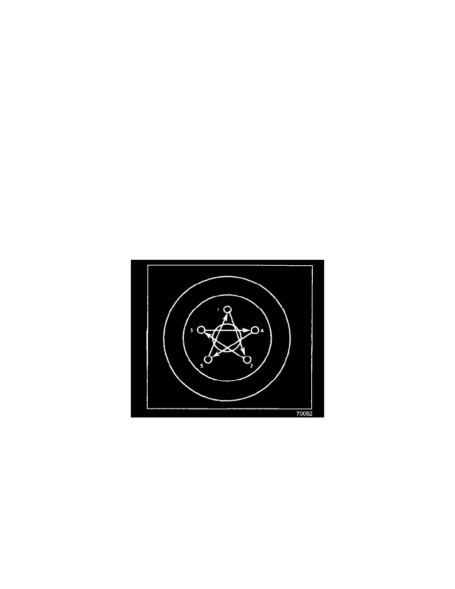
Tighten
Tighten the wheel nuts to 140 N.m (100 lb ft) with a TORQUE WRENCH following the three step method shown.
^
Hand tighten all 5 wheel nuts using the star pattern (refer to the illustration).
^
Tighten all 5 wheel nuts to approximately 1/2 specification using the star pattern.
^
Tighten all 5 wheel nuts to 140 N.m (100 lb ft) using the star pattern.
12.
Fasten a dial indicator to the steering knuckle so that the indicator needle contacts the rotor inboard friction surface approximately 12.7 mm (0.5
in) from the rotors's outer edge.
13.
Rotate the wheel on the opposite side of the vehicle and confirm that lateral run-out is less than or equal to .040 mm (.0015 in). If run-out is less
than or equal to.040 mm (.0015 in), proceed to Step 14. if run-out is greater than .040 mm (.0015 in), remove the wheel and secure the rotor using
conical retaining washers J 45101-100 and the existing wheel nuts. Measure run-out following Steps 3 and 4 above to ensure that the right
correction plate was selected and properly installed. If run-out is within specification, reinstall the wheel making sure to use the three step
tightening procedure in Step 11 and check run-out per Steps 12 and 13. If run-out is still out of specification, index the wheel or install a wheel
from another position on the car until the correct run-out specification is achieved