
Grand AM V6-3100 3.1L MFI VIN M (1994)
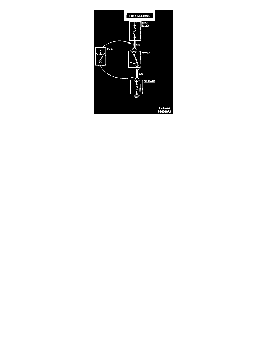
Voltage Drop Test
This test checks for voltage being lost along a wire, or through a connection or switch.
1. Connect the positive lead of a Digital Voltmeter (DVM) to the end of the wire (or to one side of the connection or switch) which is closer to the
Battery.
2. Connect the negative lead to the other end of the wire (or the other side of the connection or switch).
3. Operate the circuit.
4. The DVM will show the difference in voltage between the two points.
General
Electrical troubleshooting requires the use of common electrical test equipment.
Test Light/Digital Voltmeter
Use a test light to check for voltage. A Test Light (J 34142-B) is made up of a 12 volt light bulb with a pair of leads attached. After grounding one lead,
touch the other lead to various points along the circuit where voltage should be present. When the bulb goes on, there is voltage at the point being tested.
A Digital Voltmeter (DVM) can be used instead of a test light While a test light shows whether or not voltage is present, a DVM indicates how much
voltage is present.
An increasing number of circuits include solid state control modules. One example is the Engine Control Module (ECM). Voltages in these circuits
should be tested only with a 10-megohm or higher impedance DVM or multimeter (J 39200). Unless directed to within the diagnostics, never use a test
light on circuits that contain solid state components since damage to these components may result.
When testing for voltage or continuity at the connection, it is not necessary to separate the two halves of the connector. Unless testing a Weather Pack(R)
connector, always probe the connector from the back. Always check both sides of the connector. An accumulation of dirt and corrosion between contact
surfaces is sometimes a cause of electrical problems. Refer to Checking Terminal Contact.
Connector Test Adapters
Connector Test Adapter Kit (J 35616-A) is available for making tests and measurements at separated connectors. This kit contains an assortment of
probes which mate with many of the types of terminals you will see. Avoid using paper clips and other substitutes since they can damage terminals and
cause incorrect measurements.
Self-Powered Test Light
A self-powered test light (J 21008-A) can be used to check for continuity. This tool is made up of a light bulb, Battery and two leads. If the leads are
touched together, the bulb will go on.
A self-powered test light is used only on an unpowered circuit. First remove the fuse which feeds the circuit you're working on. Select two specific points
along the circuit through which there should be continuity. Connect one lead of the self-powered test light to each point if there is continuity, the test
light circuit will be completed and the bulb will go on.
Never use a self-powered test light on circuits that contain solid state components, since damage to these components may result.
Ohmmeter