
Grand Prix V6-191 3.1L (1989)
Technical Service Bulletin # 89319
Date: 890501
Steering - Service Manual Updates, Steering Controls
Bulletin Number:
89-3-19
Reference Number:
903201R
Publish Date:
5/89
Subject:
SERVICE MANUAL UPDATE - SECTIONS 3F AND 8A STEERING WHEEL CONTROLS
Models
Atfected:
1989 BONNEVILLE, GRAND PRIX AND 6000 MODELS
The attached Service Manual information for Sections 3F and 8A were not available when the 1989 Pontiac Bonneville Service Manual was shipped to
dealerships.
Items of special concern are use of steering wheel removal tool J 1859-03 and bulb replacement. The removal tool bolts must be installed to not more
than 5 full turns to prevent damage to the steering wheel control components in the column. Bulb replacement can be done only at Delco repair shops.
The vehicle can still be driven, and the horns are not affected by control button assembly removal. Although the 6000 and Grand Prix models have
several different functions (see Figure 2) on their control button assemblies, service procedures for the Bonneville assembly are still applicable.
SECTION 3F
STEERING WHEEL CONTROLS
NOTICE:
When fasteners are removed, always reinstall them at the same location from which they were removed. If a fastener needs to be replaced,
use the correct part number for that application. If the correct part number fastener is not available, a fastener of equal size and strength (or
stronger) may be used. Fasteners that are not reused, and those requiring thread locking compound will be called out. The correct torque
value must be used when installing fasteners that require it. If the above conditions are not followed, parts or system damage could result.
CONTENTS
CONTROLS SYSTEM COMPONENTS Steering Wheel Controls System .................... 3F-1 Control Button Functions ................................3F-2 UNIT
REPAIR Control Buttons Assembly ..............................3F-2
Bulb Service ..............................................3F-2 Horn Pad ..................................................3F-2 Steering Wheel ..........................................3F-2 Control
Buttons .........................................3F-3 Delay Relay and Interface Module ...............3F-3
Controls System Components
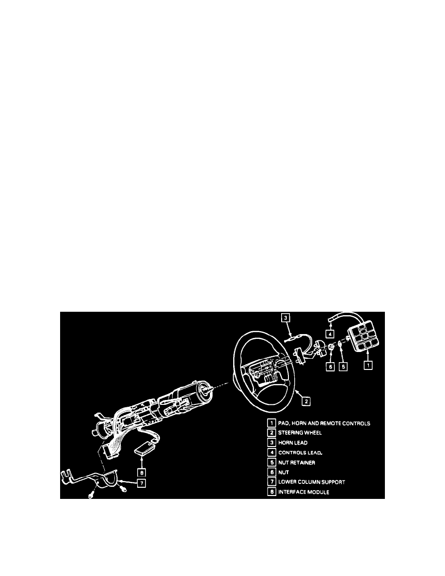
Figure 1 - Steering Wheels Controls Components
Figure 1
The steering wheel remote control pad (1) is removed by carefully prying out the pad, and disconnecting the horn (3) and controls (4) leads. The delay
relay (9) and interface module (8) convert and relay the control button signals to the proper function.