
Grand Prix V6-191 3.1L (1989)
Steering Wheel Controls (UK3) Description (Transport)
CIRCUIT OPERATION
The Steering Wheel Controls consist of several components. They include the following:
^
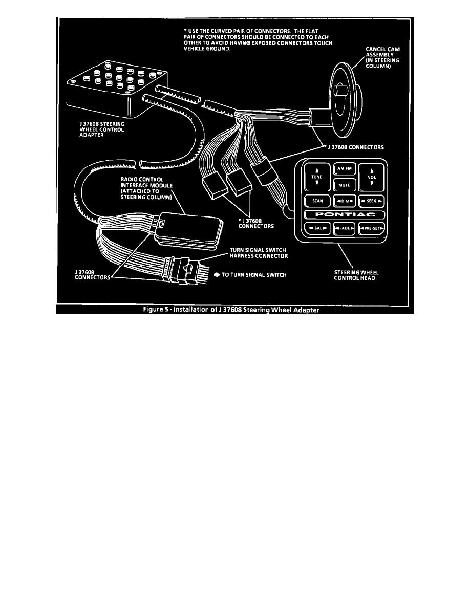
Turn Signal Switch
^
Cancel Cam Assembly
^
Steering Wheel Control Head
^
Radio Control Interface Module
STEERING WHEEL CONTROL HEAD
The Steering Wheel Control Head controls the Radio by creating voltage places that correspond to different Radio control functions. These signals are
sent to the optical receiver/transmitters in the Cancel Cam Assembly. The Steering Wheel Control Head also receives data line signals via the Cancel
Cam Assembly. The signals received by the Control Head are used to determine when the data line is free of other signals so it may transmit. The
Steering Wheel Control Head receives power, illumination and ground via slip rings between the Turn Signal Switch and the Cancel Cam.
CANCEL CAM ASSEMBLY
The Cancel Cam Assembly includes five solid state infrared transmitter/receiver units. These units along with two identical optical units in the Turn
Signal Switch are used to send optical signals between the Steering Wheel and Steering Column. The optical units are arranged so they are always in
sight of each other and thus form an optical slip ring. The Cancel Cam incorporates circuitry which changes the signals from optical to electrical and vice
versa. The Cancel Cam Assembly receives power, ground and illumination power through three of its four slip rings from the Turn Signal Switch brush
contacts. The Horn Switch signal is sent through the fourth slip ring.
TURN SIGNAL SWITCH
The Turn Signal Switch receives optical signals from the Cancel Cam Assembly and converts them to electrical signals that are sent to the Radio Control
Interface Module on a one-way data bus. It also receives electrical signals from the Radio Control Interface Module on a one-way data bus and converts
them to optical signals which are sent to the Cancel Cam Assembly. The Turn Signal Switch sends power, ground and illumination power to the Cancel
Cam Assembly through its brush contacts.
RADIO CONTROL INTERFACE MODULE
The Radio Control Interface Module receives electrical voltage pulses from the Turn Signal Switch (DATA IN) and sends these signals to the Radio over
the serial data line. It also receives signals from other devices over the serial data line and sends these signals through the Turn Signal Switch and Cancel