
Grand Prix V6-191 3.1L VIN M SFI (1998)
Diagnostic System Check (Part 4 Of 4)
SYSTEM DESCRIPTION
The Body Control Module (BCM) Diagnostic System Check is an organized approach to identify problems associated with the BCM. This check
must be the starting point for any BCM complaint, and will direct you to the next logical step in diagnosing the complaint. The BCM is a very
reliable component and is not likely the cause of the malfunction. Most system complaints are linked to faulty wiring and connectors, and
occasionally to components. Understanding the computer system and using the tables correctly will reduce diagnostic time and prevent
unnecessary parts replacement.
DIAGNOSTIC AIDS
^
The following conditions may result in an intermittent operation of the BCM with no DTC stored:
-
Any condition which results in the interruption of power to the BCM.
-
Out of range battery voltage specification. Normal battery voltage: 9-16v.
-
A loose or damaged ground(s).
^
An intermittent failure in the electronic system may be very difficult to detect and to accurately diagnose. The BCM tests for different
malfunctions under different vehicle conditions. For this reason, a thorough test drive is often needed in order to repeat a fault condition. If the
system malfunction is not repeated during the test drive, a good description of the complaint may be very useful in locating an intermittent fault
condition. Faulty electrical connections or wiring causes most intermittent problems. When an intermittent condition is suspected, check the
suspected circuits for the following conditions:
-
Poor mating of connector halves or backed out terminals.
-
Improperly formed or damaged terminals.
-
Wire chafing.
-
Poor wire to terminal connections.
-
Dirty or corroded terminals.
-
Damage to connector bodies.
^
Use a J 35616-A whenever a diagnostic procedure requests probing or checking a terminal. Using this will ensure that no damage to the terminal
will occur and will give an idea of whether contact tension is sufficient.
^
DTC P1626 will set in the Powertrain Control Module (PCM) when the ignition switch is in the RUN position with the Body Control Module
(BCM) disconnected. When BCM diagnostics and repairs are completed, refer to the additional information on PCM related DTCs.
TEST DESCRIPTION
Numbers below refer to the step numbers on the diagnostic table.
1. Checks if the BCM identifies its BCM type.
2. Checks if vehicle has correct BCM type installed.
3. Checks for DTCs stored in BCM memory.
5. Checks for a short to ground in circuit 240.
7. Checks for a short to ground in circuit 1540.
9. Checks for a short to ground in circuit 39.
11. Checks for a short to ground in circuit 443.
12. Checks for an open in circuit 1550.
13. Checks for an open in circuit 240.
14. Checks for an open in circuit 1540.
15. Checks for an open in circuit 39.
16. Checks for a short to B+ in circuit 39.
17. Checks for an open in circuit 443.
18. Checks for a short to B+ in circuit 443.
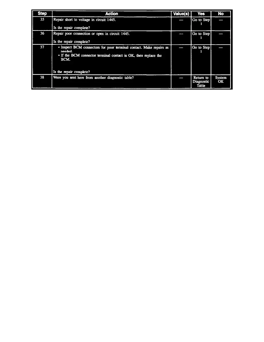
19. Checks for a short to B+ in circuit 1445.
20. Checks for an open in circuit 1445.