
Grand Prix V6-191 3.1L VIN M SFI (1998)
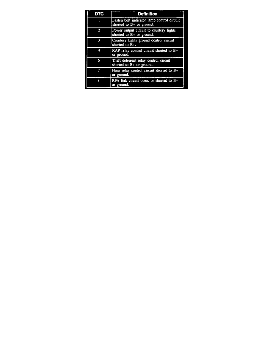
DTC Table
CLEARING DIAGNOSTIC TROUBLE CODES (DTCS)
To erase DTCs stored in the Body Control Module (BCM), press and hold unlock on either power door lock switch for 4 seconds.
Step 4: Entering the Input/Output Test
After the Body Control Module (BCM) reads all DTCs in memory, the BCM enters the Input/Output test.
The BCM flashes the fasten belts indicator and sounds the chime once when operating one of these inputs:
^
All reading courtesy light switches.
^
Door lock cylinders.
^
Driver's door lock ajar switch.
^
Driver's fasten seat belt switch.
^
Driver Information Display (DID).
^
Headlamps OFF switch.
^
IP compartment lamp switch.
^
Keyless entry requests for door lock/unlock.
^
Passenger door lock ajar switch.
^
Power door lock switches.
^
Rear compartment courtesy lamp switch.
^
Shock sensor.
^
Sunshade illuminated mirrors.
^
Trip calculator.
^
Turn signal switch.
If the BCM does not provide a chime feedback, then there is an open or short in that circuit or a faulty component.
Perform the following procedure to test BCM outputs:
1. Make sure the BCM is in diagnostics mode.
2. Turn the IP dimmer switch to the DOME position.
The BCM entered the output test, which consists of:
^
Test 1: De-energizes circuit 1393, turn off all of the interior lights.
^
Test 2: Energizes circuit 1393, providing power to all of the interior lights.
^
Test 3: Grounds circuit 690, turning on all courtesy lights.
^
Test 4: Energizes the theft deterrent relay for 1 second by grounding circuit 352, turning on the headlamps (BCM type 4 only).
^
Test 5: Energizes the horn relay for 25 ms by grounding circuit 28, sounding the horn (BCM type 4 only).
^
Test 6: Turns on the theft deterrent indicator lamp by grounding circuit 749 (BCM type 4 only).
^
Test 7: Turns off the theft deterrent indicator lamp by opening circuit 749 (BCM type 4 only).
The BCM runs the output test in numerical order.
To move to the next test, cycle the IP dimmer switch from the DOME position, to off, back to DOME. The BCM sounds the chime a number equivalent
to the output test number above.
Step 5: Exiting Diagnostics
Perform the following procedure to exit the Body Control Module (BCM) diagnostics mode, and return to normal BCM operation.
1. Turn the ignition switch to the OFF position.
2. Reinstall the MALL PGM fuse.
3. Turn the ignition switch to the RUN position.