
Grand Prix V6-204 3.4L DOHC (1992)
Knock Sensor: Testing and Inspection
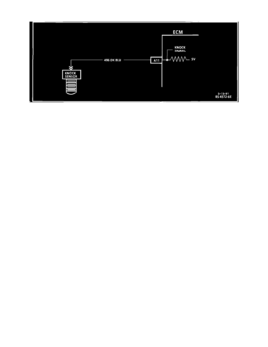
Electronic Spark Control (ESC - Knock Sensor) Circuit Diagram
CIRCUIT DESCRIPTION:
The knock sensor is used to detect engine detonation and the PCM will retard the electronic spark timing based on the signal being received, The
circuitry within the knock sensor causes the PCM's supplied 5 volt signal to be pulled down so that under a no knock condition, CKT 496 would measure
about 2.5 volts.
The knock sensor produces an AC signal which rides on the 2.5 volts DC voltage. The amplitude and frequency are dependent upon the intensity of the
knock.
The Mem-Cal used with this vehicle contains the functions which were part of the remotely mounted ESC modules used on other GM vehicles. The ESC
portion of the Mem-Cal then sends a signal to other parts of the PCM which adjusts the spark timing to reduce detonation.
TEST DESCRIPTION