
Grand Prix V6-204 3.4L DOHC VIN X SFI (1995)
Convertible Top: Initial Inspection and Diagnostic Overview
Circuit Operation
With the Ignition Switch in "RUN", voltage is applied through Fuse 6 to the Folding Top Pump Motor Relay. The Folding Top Switch is powered Hot at
all times through Fuse 19.
When the Folding top Switch is in the "Down" position, voltage is applied to the "Top Down" coil in the Folding Top Pump Motor Relay, energizing it
and powering the Folding Top Pump Motor. The motor runs a pump which hydraulically lowers the Convertible Top.
Circuit operation is similar when the Switch is in the "UP" position. Voltage polarity to the motor is now reversed and the hydraulic pump now raises the
Convertible Top.
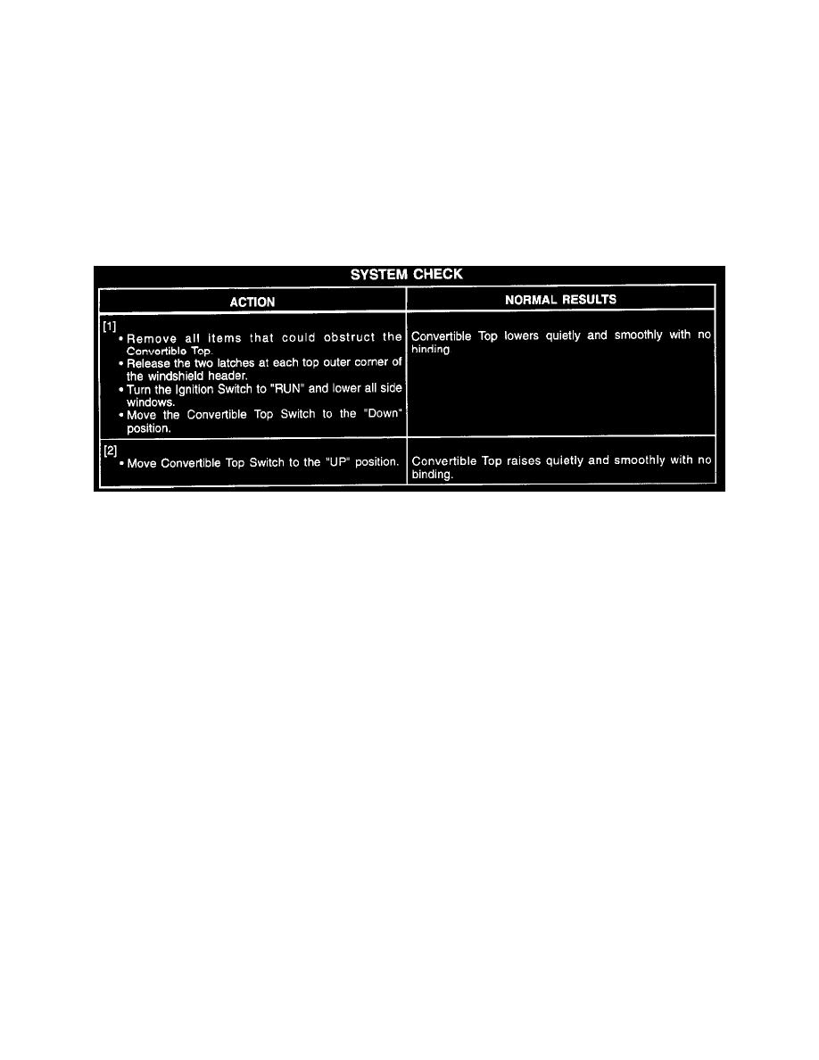
System Check
System Check
A malfunction in the electrical system may be caused by a low Battery, breaks in wiring, improper connections, inoperative electrical component, or
wires or components shorting to one another or to body metal. Before beginning checking procedure. To help diagnose a Convertible Top system
electrical malfunction, see Troubleshooting Hints and System Diagnosis.
See: Troubleshooting Hints
See: Diagnostic Trouble Code Tests and Associated Procedures
Troubleshooting Hints
IMPORTANT: To avoid misdiagnosis, check linkage for mechanical binding which would prevent correct system operation.
1. Check Fuses 6 and 19.
2. Check that ground G304 is clean and tight.
3. If a motor's internal circuit breaker trips, it will not reset until voltage is removed from the motor.
4. If system checks OK electrically, refer to Brakes and Traction Control for hydraulic system diagnosis. See: Brakes and Traction Control
^
Check for a broken (or partially broken) wire inside of the insulation which could cause system malfunction but prove "GOOD" in a
continuity/voltage check with a system disconnected. These circuits may be intermittent or resistive when loaded, and if possible, should be
checked by monitoring for a voltage drop with the system operational (under load).
^
Check for proper installation of aftermarket electronic equipment which may affect the integrity of other systems (refer to General
Troubleshooting Procedures). See: Diagrams/Diagnostic Aids
^
Refer to System Diagnosis. See: Diagnostic Trouble Code Tests and Associated Procedures