
Grand Prix V6-204 3.4L DOHC VIN X SFI (1995)
4. Door trim panel.
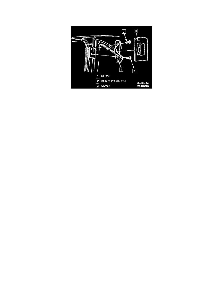
Coupe
Power Lock Actuator
Remove or Disconnect
1. Door trim panel.
2. Loosen water deflector.
3. Nut and screw securing cover assembly to door.
4. Door handle cover assembly.
5. Lock cylinder to lock rod.
6. Outside handle lock rod.
7. Screws securing lock assembly to door.
8. Rivets securing lock module assembly to door by punching out mandrel, then using a 3/16 inch drill bit.
9. Power lock connector.
10. Lock module assembly.
Install or Connect
1. Lock module assembly in position through access hole in door inner panel. Align module to hole in door facing.
NOTICE: It is required that while performing step 2 the lock assembly be held tight against door facing while installing screws. All screws must be
driven at a 90° angle to door facing to prevent cross threading or stripping of screws or door lock attachment holes. It is required to tighten screws to
specific torque of 7 N.m (62 lb. in.).
2. Screws securing lock assembly to door.
Tighten
^
Screws to 7 N.m (62 lb. in.).
3. Power lock connector.
4. Rivets securing lock module assembly to door using 3/16 inch x 1/4 inch peel type rivets.
5. Outside handle to lock rod.
6. Lock cylinder to lock rod.
Inspect
^
Lock system for proper operation.
7. Door handle cover assembly.
8. Nut and screw securing cover assembly to door.
Tighten
^
Nut to 3 N.m (27 lb. in.).
^
Screw to 2 N.m (18 lb. in.).
9. Water deflector.
10. Door trim panel.