
Grand Prix V6-204 3.4L DOHC VIN X SFI (1995)
6. Power lock connector.
7. Lock module.
8. Handle to lock rod, if replacing.
Install or Connect
1. Handle to lock rod, if removed.
2. Lock module in position through access hole in door inner panel.
A. Install handle to lock rod to handle lever.
B. Align module to holes in door facing.
NOTICE: It is required that while performing step 3 that the lock assembly be held tight against door facing while installing screws. All screws must
be driven at a 90 degree angle to door facing to prevent cross threading or stripping of screws or door lock attaching holes. It is also required to
screws to specified torque of 7 N.m (62 lb. in.).
3. Screws.
Tighten
^
Screws to 7 N.m (62 lb. in.).
4. Power lock connector.
5. Rivets using 3/16 inch x 1/4 inch peel type rivets.
6. Lock cylinder to lock rod.
Inspect
^
Lock system for proper operation.
7. Water deflector.
8. Trim panel.
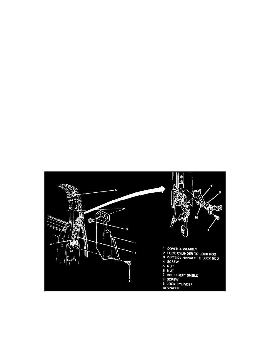
Coupe
Door Lock At Handle
Remove or Disconnect
1. Screw and nut securing cover assembly to door.
2. Cover assembly.
3. Lock cylinder to lock rod.
4. Screw securing anti-theft shield.