
Grand Prix V6-3.1L VIN J (2000)
Oxygen Sensor: Diagnostic Aids
Additional Diagnostic Information
The GM Diagnostic Worksheet has been designed to improve communications between the service customer and the technician. The diagnostic
worksheet can provide the technician with more information than the conventional repair order, since it is filled out by the service customer. The GM
Diagnostic Worksheets are available to you at no cost. GM Service Bulletin 58-01-01 has information on how to order this diagnostic worksheet.
Basic Knowledge Required
Without a basic knowledge of electricity, it will be difficult to use the diagnostic procedures contained in this section. You should understand the basic
theory of electricity and know the meaning of voltage (volts), current (amps) and resistance (ohms). You should understand what happens in a circuit
with an open or a shorted wire. You should be able to read and understand a wiring diagram.
Refer to Strategy Based Diagnosis in General Information in order to properly diagnose and repair the customer concern.
Checking Aftermarket Accessories
Do not connect aftermarket accessories into the following circuits:
CAUTION: Refer to SIR Service Precautions Caution in Service Precautions.
^
SIR circuits, all such circuits are indicated on circuit diagrams with the SIR symbol.
NOTE: Refer to OBD II Symbol Description Notice in Service Precautions.
^
OBDII circuits, all such circuits are indicated on circuit diagrams with the OBDII symbol.
Always check for aftermarket accessories (non-OEM) as the first step in diagnosing electrical problems. If the vehicle is so equipped, disconnect the
system to verify that these add-on accessories are not the cause of the problems.
Possible causes of vehicle problems related to aftermarket accessories include:
^
Power feeds connected to points other than the battery.
^
Antenna location.
^
Transceiver wiring located too close to vehicle electronic modules or wiring.
^
Poor shielding or poor connectors on antenna feed line.
^
Check for recent service bulletins detailing installation guidelines for aftermarket accessories.
Circuit Breakers
A circuit breaker is a protective device that is designed to open the circuit when a current load is in excess of the rated breaker capacity. If there is a short
or other type of overload condition in the circuit, the excessive current will open the circuit between the circuit breaker terminals. Two types of circuit
breakers are used.
Circuit Breaker: This type opens when excessive current passes through it for a period of time. It closes again after a few seconds, and if the cause of
the high current is still present, it will open again. The circuit breaker will continue to cycle open and closed until the condition causing the high current
is removed.
Positive Temperature Coefficient (PTC) Circuit Breaker: This type greatly increases its resistance when excessive current passes through it. The
excessive current heats the PTC device, as the device heats its resistance increases. Eventually the resistance gets so high that the circuit is effectively
open. Unlike the ordinary circuit breaker the PTC unit will not reset until the circuit is opened, by removing the voltage from its terminals. Once the
voltage is removed the circuit breaker will re-close within a second or two.
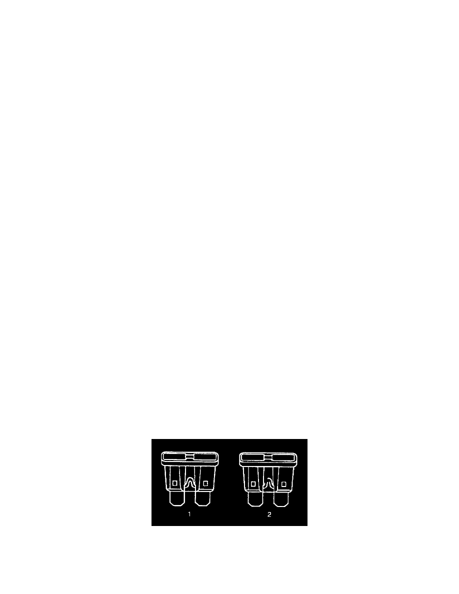
Fuses
Circuit Protection - Fuses