
Grand Prix V6-3.8L SC VIN 1 (1997)
Power Steering Hose/pipe (3100 Engine)
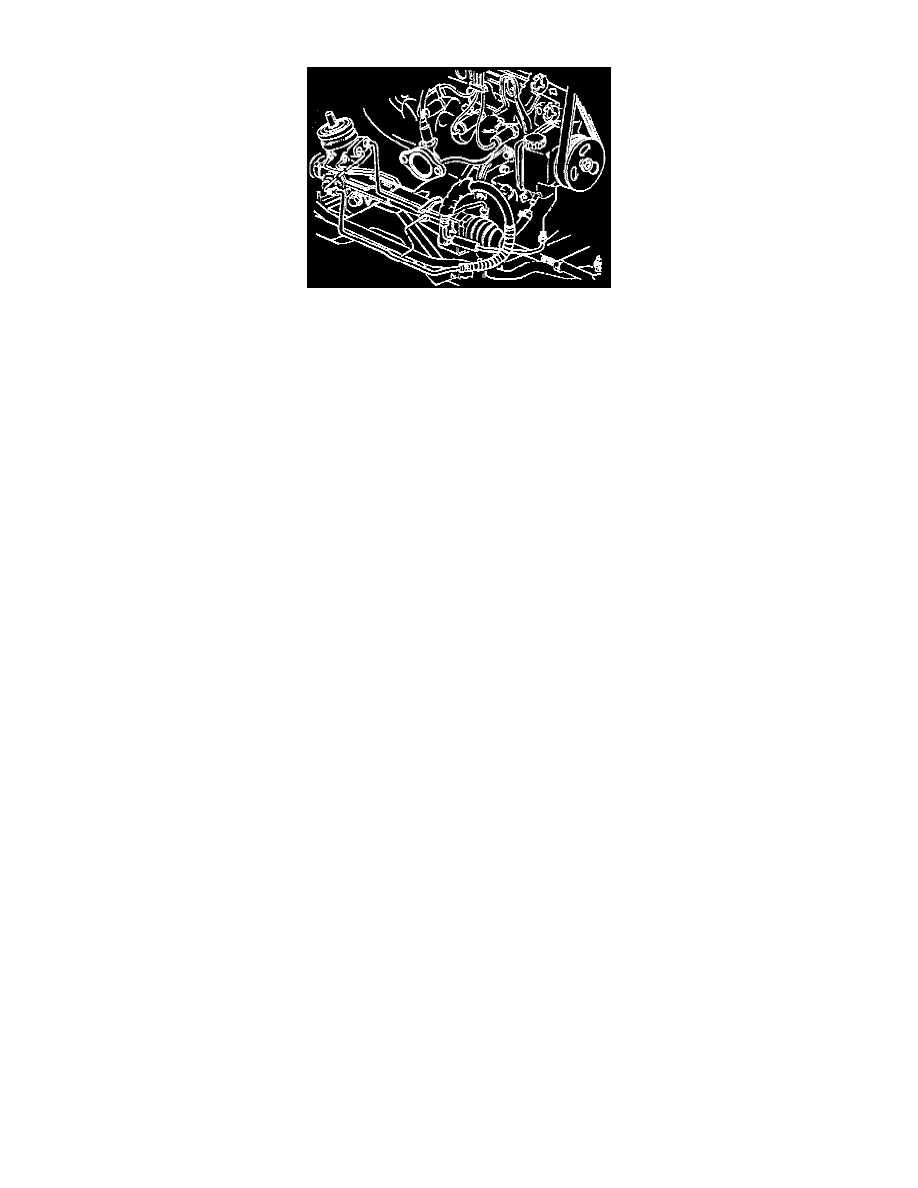
Power Steering Hose/pipe Routing (3800 Engine)
REMOVE OR DISCONNECT
1. Place drain pan under pump and gear.
2. Engine mount strut at engine.
3. Reservoir inlet hose from pump.
4. Tie straps from hose.
5. Raise and suitably support vehicle.
CAUTION: Failure to disconnect intermediate shaft from power steering gear stub shaft can result in damage to steering gear and/or
intermediate shaft. This damage can cause loss of steering control which could result in personal injury.
NOTICE: Set steering shaft so block tooth on upper steering shaft is at the 12 o'clock position, wheels on vehicle are straight ahead and set
ignition switch to "LOCK" position. Failure to follow these procedures could result in damage to the Supplemental Inflatable Restraint (SIR) coil.
6. Intermediate steering shaft lower bolt and move plastic cover aside.
7. Support frame using jack stands.
NOTICE: Do not lower rear of frame too far as damage to engine components nearest to the cowl may result.
8. Rear frame bolts and lower rear of frame.
9. Inlet hose from steering gear.
10. Cooling pipe from steering gear.
11. Power steering gear pipe from clip.
12. Cooling pipe from frame.
13. Cooling pipe and reservoir inlet hose from vehicle.
14. Cooling hose clamp.
15. Cooling pipe.
INSTALL OR CONNECT
NOTICE: Always use the correct fastener in the proper location. When you replace a fastener, use ONLY the exact part number for that application.
The manufacturer will call out those fasteners that require a replacement after removal. The manufacturer will also call out the fasteners that require
thread lockers or thread sealant. UNLESS OTHERWISE SPECIFIED, do not use supplemental coatings (paints, greases, or other corrosion inhibitors)
on threaded fasteners or fastener joint interfaces. Generally, such coatings adversely affect the fastener torque and the joint clamping force, and may
damage the fastener. When you install fasteners, use the correct tightening sequence and specifications. Following these instructions can help you
avoid damage to parts and systems.
1. Position cooling pipe to reservoir inlet hose until properly seated (3100 engine only) or position cooling pipe to pump inlet nipple until seated
(3800 engine only).
2. Power steering gear outlet hose clip.
3. Position and align clips to cooling pipe.
4. Position cooling pipe to frame.
5. Power steering gear pipe clips.
6. Power steering gear pipe to clip.
7. Cooling pipe fitting to steering gear.
^
Tighten pipe fitting to 27 Nm (20 ft. lbs.).
8. Inlet hose to steering gear.
9. Power steering gear outlet hose clip.
10. Raise frame.