
Grand Prix V6-3.8L VIN 2 (2004)
Steps 1 - 9
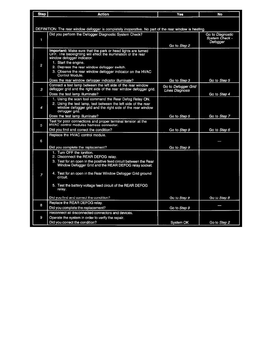
The numbers below refer to the step numbers on the diagnostic table.
3. This step tests for voltage at the defog grid. If the voltage signal is present the malfunction is in the grid.
4. If the relay can be commanded ON then the malfunction is in the message sent from the HVAC module.
7. This step completely test all of the output wiring of the circuit. If no malfunction is fond in this step then the relay is the cause of the concern. The
BCM has integral diagnostic capabilities to analyze the control side of the relay. If no code is set for the control circuit and the relay can be
commanded ON and OFF then the relay is at fault.