
Grand Prix V6-3100 3.1L MFI VIN M (1994)
Knock Sensor: Description and Operation
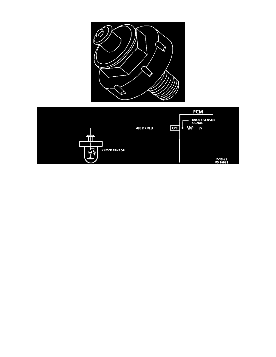
Knock Sensor Circuit Diagram
PURPOSE
The knock sensor is used to detect engine detonation. The control unit uses this signal to retard ignition timing when a knock occurs. This helps to
maintain optimum ignition timing advance while avoiding damaging (and annoying) engine "PING" or "KNOCK" due to detonation in the
combustion chambers.
OPERATION
The circuitry, within the knock sensor, causes the ECM's 5.0 volts to be pulled down so that under a no knock condition, CKT 496 would measure
about 2.5 volts. The knock sensor produces an AC signal, which rides on the 2.5 volts DC voltage. When a knock occurs, the resultant voltage
"spike" from the sensor oscillates about this 2.5 volt "bias". This voltage "spike" rises above the thresh-hold voltage (about 3 volts) indicating an
engine knock. When the control module receives a "Knock" signal, It responds by retarding the ignition timing. When the knocking stops, the
control module advances the timing in small increments back to its preset value. This allows the PCM to maintain optimum ignition timing
advance for better fuel economy and performance under all operating conditions.