
Grand Prix V8-5.3L (2007)
4. Install the screws to the mode actuator (1).
Tighten the screws to 1.5 N.m (13 lb in).
5. Connect the electrical connector to the mode actuator.
6. Install the I/P compartment.
7. Install the right I/P insulator.
8. Calibrate the actuator. Refer to Re-Calibrating Actuators. See: Testing and Inspection/Programming and Relearning
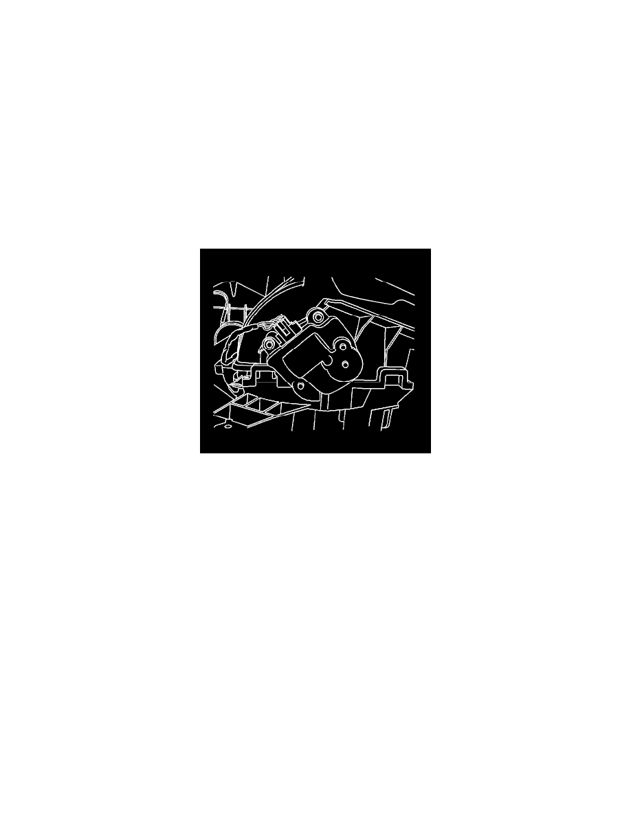
Recirculation Actuator Replacement
Recirculation Actuator Replacement
Removal Procedure
1. Remove the right instrument panel (I/P) insulator.
2. Remove the I/P compartment.
3. Remove the screws that secure the recirculation actuator to the HVAC module assembly.
4. Remove the recirculation actuator from the HVAC module assembly.
5. Disconnect the electrical connector from the recirculation actuator.
Installation Procedure
1. Position the recirculation actuator, aligning the slots in the electric actuator drive to the flats on the shaft.
2. Align the locating hole to the alignment pin on the HVAC module assembly.
3. Slide the actuator drive completely onto the shaft, with the mounting holes flush with the mounting screw holes on the HVAC module assembly.