
Grand Prix V8-5.3L (2007)
Main Relay (Computer/Fuel System): Testing and Inspection
Powertrain Relay Diagnosis
Diagnostic Fault Information
Always perform the Diagnostic System Check - Vehicle prior to using this diagnostic procedure. See: Testing and Inspection/Initial Inspection and
Diagnostic Overview/Diagnostic System Check - Vehicle
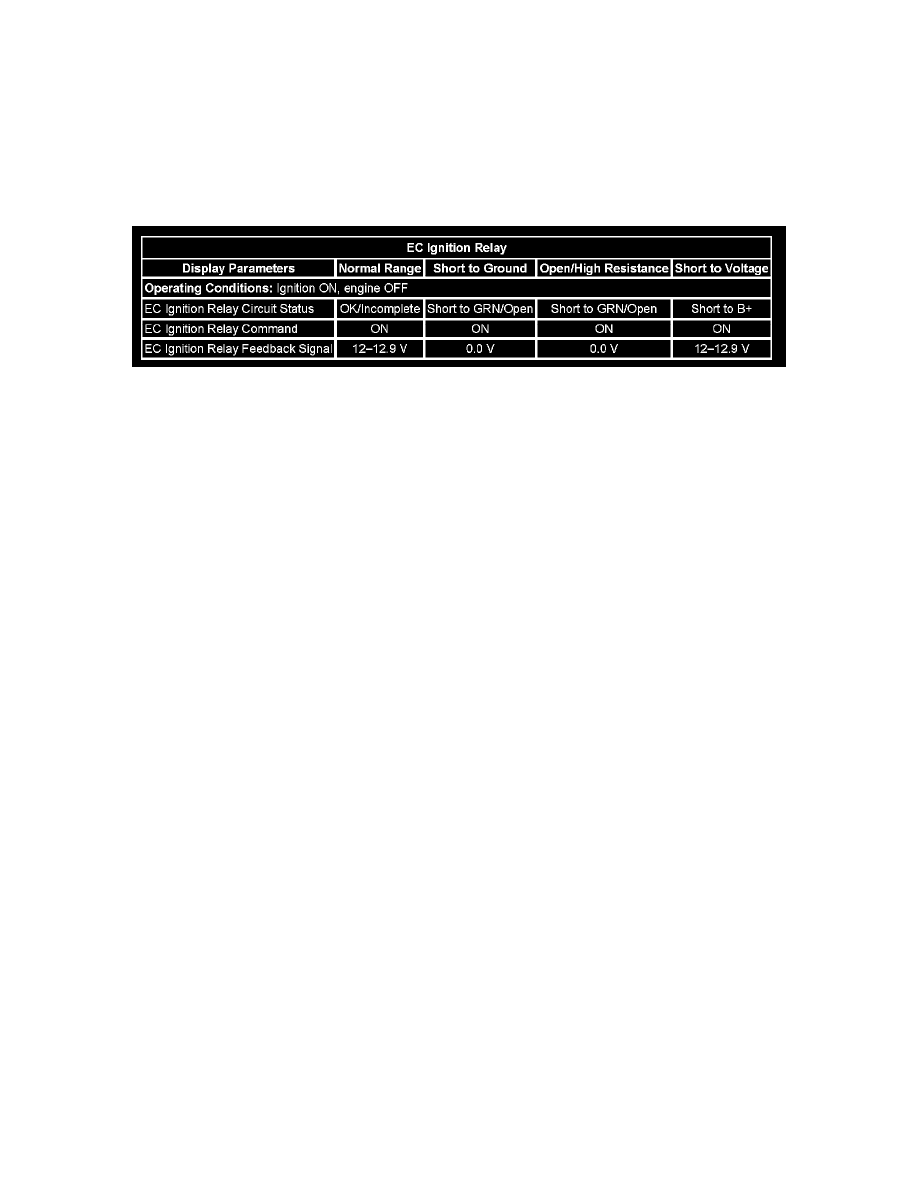
Typical Scan Tool Data
Circuit/System Description
The powertrain relay is a normally open relay. The relay armature is held in the open position by spring tension. Battery positive voltage is supplied
directly to the relay coil and the armature contact at all times. The engine control module (ECM) supplies the ground path to the relay coil control circuit
via an internal integrated circuit called an output driver module (ODM). The ODM output control is configured to operate as a low side driver for the
powertrain relay. The ODM for the powertrain relay also incorporates a fault detection circuit, which is continuously monitored by the ECM. When the
ECM commands the powertrain relay ON, ignition 1 voltage is supplied to the ECM, and to several additional circuits.
Diagnostic Aids
This test procedure requires that the vehicle battery has passed a load test and is completely charged. Refer to Battery Inspection/Test. See: Starting and
Charging/Testing and Inspection/Component Tests and General Diagnostics/Battery Inspection/Test
Special Tools Required
*
J 35616 Connector Test Adapter Kit
*
J 43244 Relay Puller Pliers
J 35616 Connector Test Adapter Kit
Circuit/System Verification
1. Ignition ON, engine OFF, command the powertrain relay ON and OFF several times using the scan tool output control function. You should either
hear or feel the relay click with each command.
2. Ignition ON, engine OFF, with a test lamp, probe both test points of all the fuses that are powered by the powertrain relay. The test lamp should
illuminate on at least one test point of each fuse.
^
If the vehicle passes the Circuit/System Verification test, then operate the vehicle within the Conditions for Running the DTC. You may also
operate the vehicle within the conditions that are captured in the Freeze Frame/Failure Records Data list.
Circuit/System Testing
1. Ignition OFF, disconnect the powertrain relay.
2. Ignition ON, verify that a test lamp does not illuminate between the relay coil control circuit and ground.
^
If the test lamp illuminates, test the relay coil control circuit for a short to voltage. If the circuit tests normal, replace the ECM.
3. Verify that a test lamp does not illuminate between the relay ignition 1 voltage circuit and ground.
^
If the test lamp illuminates, test the relay ignition 1 voltage circuit for a short to voltage. If the circuit tests normal, replace the ECM.
4. Verify that a test lamp illuminates between the relay coil B+ and ground.
^
If the test lamp does not illuminate, test the relay coil B+ circuit for a short to ground or an open/high resistance.