
GTO V8-6.0L VIN U (2005)
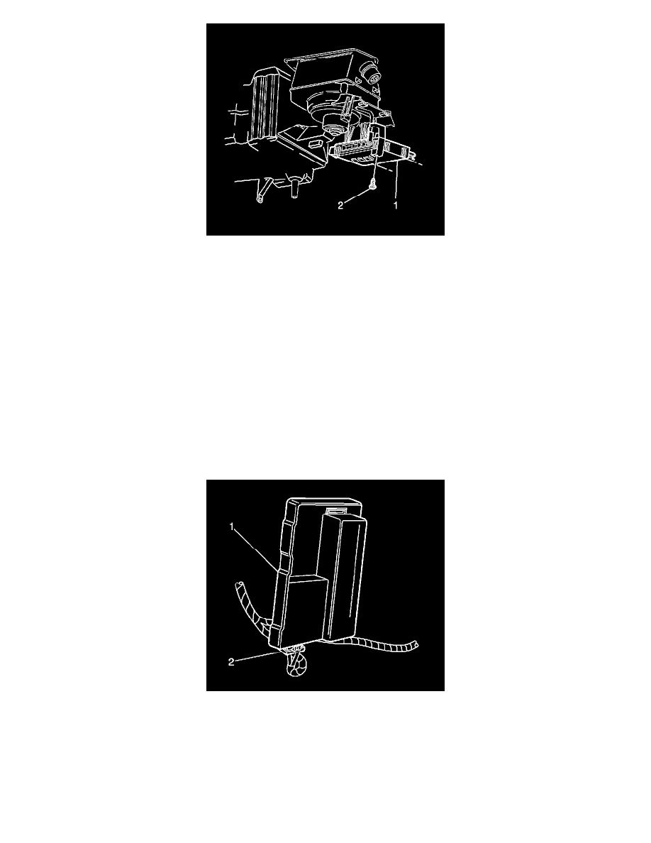
1. Align the BCM (1) to the bracket, making sure the retaining tabs are correctly located.
2. Install the screw (2) attaching the BCM (2) to the bracket.
NOTE: Refer to Fastener Notice in Service Precautions.
Tighten the screw to 2 N.m (18 lb in).
3. Connect the 4 BCM electrical connectors.
4. Install the right closeout insulator/trim panel.
5. Perform the new BCM setup. Refer to Body Control Module (BCM) Programming/RPO Configuration in Computer/Integrating Systems. See:
Testing and Inspection/Programming and Relearning
6. Program the transmitters. Refer to Transmitter Programming in Keyless Entry. See: Testing and Inspection/Programming and Relearning
Powertrain Interface Module (PIM) Replacement
POWERTRAIN INTERFACE MODULE (PIM) REPLACEMENT
REMOVAL PROCEDURE
1. Disconnect the electrical connector (2) from the (PIM) control module.
2. Remove the powertrain interface module (PIM) control module (1) from the vehicle.
INSTALLATION PROCEDURE