
GTO V8-6.0L VIN U (2005)
9. Clear a space on the ground about 1.85 m (6 ft) in diameter for deployment of the module. If possible, use a paved, outdoor location free of
activity. Otherwise, use a space free of activity on the shop floor. Make sure you have sufficient ventilation.
10. Make sure no loose or flammable objects are in the area.
11. Place the J 39401-B in the center of the cleared area.
12. Fill the fixture plastic reservoir with water or sand.
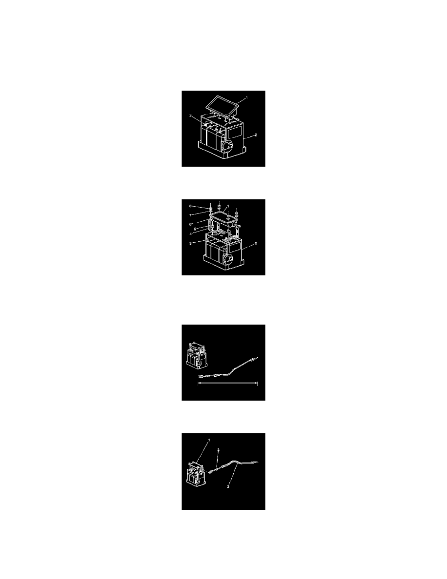
13. Mount the module in the SIR deployment fixture with the vinyl trim cover facing up using one of the following mounting methods.
IMPORTANT: Securely hand tighten all fasteners prior to deployment.
14. To use the stud mount method, remove the original mounting nuts.
15. Use the J 39401-1 mounting nuts (3) in order to secure the module (1) to the fixture (2).
16. To use the flange mount method, use 4 of the J 39401-13 hold-down nuts whenever possible in order to secure the module to the fixture.
17. If clearance restrictions do not allow the use of the J 39401-13 hold-down nuts, use four M 6 bolts (6), nuts (8), and washers (7) in order to
properly secure the I/P module (1) to the deployment fixture.
18. Securely tighten all fasteners prior to deployment.
19. Extend the SIR deployment harness and adapter to full length from the module.
20. Place a 12 volt minimum/2 amp minimum power source, i.e., vehicle battery, near the shorted end of the harness.
21. Connect the module (1) to the adapter (2) on the SIR deployment harness (3).
22. Firmly seat the adapter into the module connector.
23. Clear the area of people.