
GTO V8-6.0L VIN U (2005)
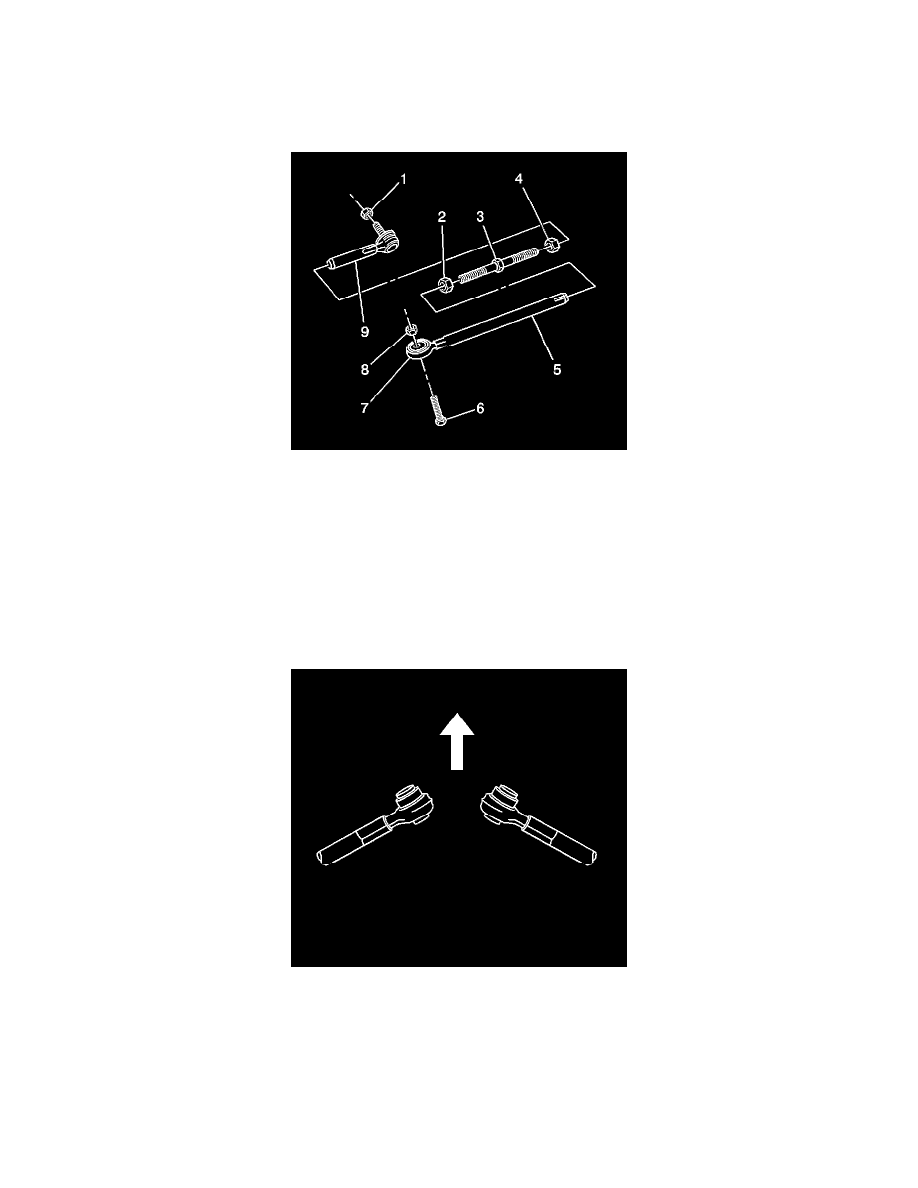
5. Important: Count the turns necessary for removal of the outer adjustment link (9).
Remove the outer adjustment link from the center adjuster.
Assemble Procedure
1. Important: Do not tighten the nuts yet. The weight of the vehicle must be on the tire and wheel assemblies before tightening the suspension
fasteners.
Thread the outer adjustment link (9) to the center adjuster (3) the same number of turns as for the removal.
2. Align the match marks on the outer adjuster lock nut (4) and on the center adjuster.
3. Thread the inner adjustment link (5) to the center adjuster the same number of turns as for the removal.
4. Align the match marks on the inner adjuster lock nut (2) and on the center adjuster.
5. Ensure the distance between the lock nuts is the same as during the removal.
6. Remove the adjustment link from the vise.
Installation Procedure
1. Important: The protruding side of the bushing must be toward the front of the vehicle.
Install the inner adjustment link to the rear suspension support.
2. Important: Do not tighten the nuts or the bolts. The weight of the vehicle must be on the tire and wheel assemblies before tightening the nuts and
the bolts.
Install the NEW nut and the bolt in order to retain the inner adjustment link to the rear suspension support.
3. Clean the stud on the outer adjustment link.