
J2000/Sunbird V6-191 3.1L (1992)
Hydraulic Modulator Assembly: Service and Repair
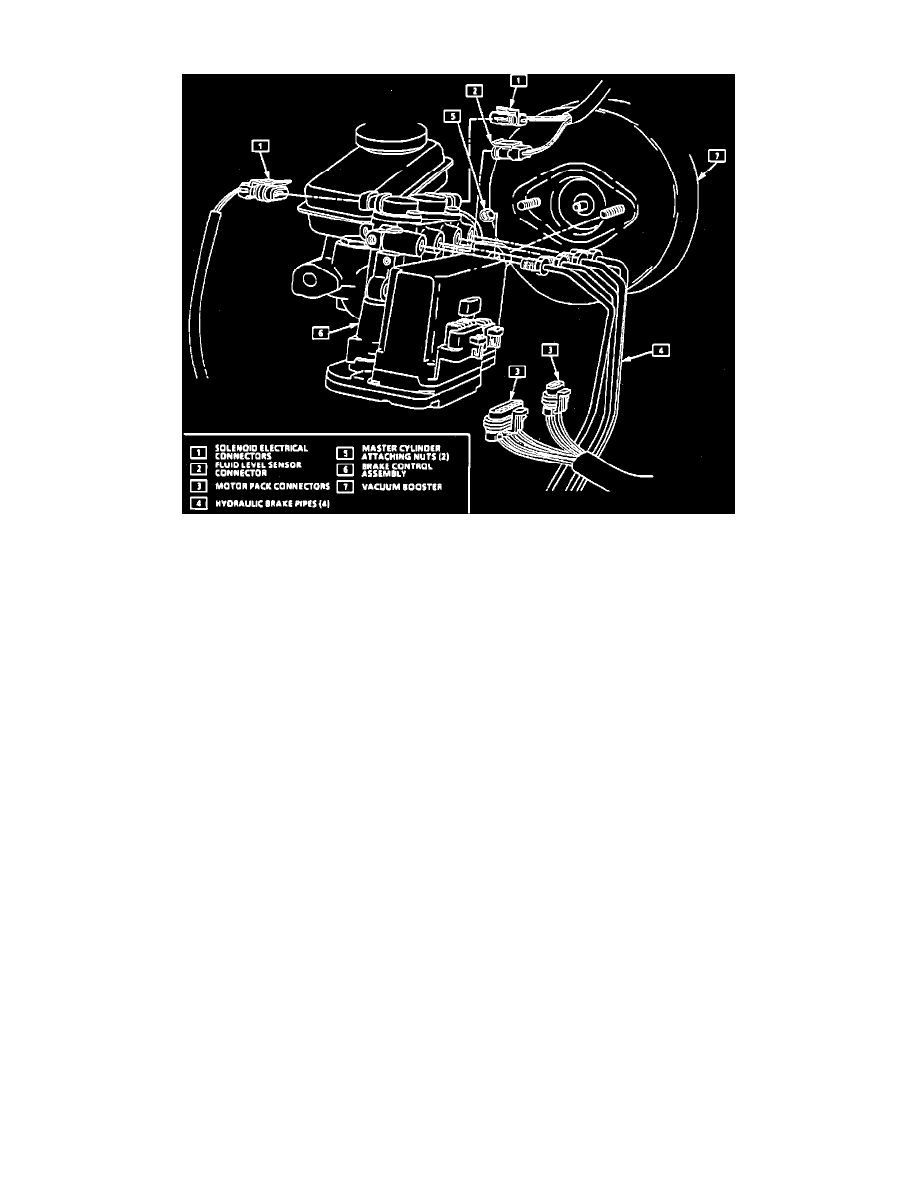
Fig. 71 ABS Hydraulic Modulator Assembly Removal
To avoid personal injury, due to a retained load on the modulator assembly, the "Gear Tension Relief" function of the TECH 1 scan tool
must be performed prior to removal of the brake control and motor assembly.
1.
Disconnect battery ground cable.
2.
Disconnect two solenoid electrical connectors, Fig. 71.
3.
Disconnect fluid level sensor connector, then the 6-pin and 3-pin motor pack electrical connectors.
4.
Place a shop cloth on top of motor pack to catch any dripping hydraulic fluid, then disconnect four hydraulic pipes from modulator assembly. Plug
open lines to prevent any fluid loss.
5.
Remove two modulator assembly to brake booster attaching nuts. It may be necessary to remove vacuum check valve from the booster to gain
access to nut closest to check valve.
6.
Remove modulator assembly from vehicle.
7.
Reverse procedure to install, noting the following:
a. Torque modulator assembly to booster attaching nuts to 20 ft. lbs.
b. Torque hydraulic pipe nuts to 13 ft. lbs.
c. Bleed hydraulic system as described under DISC AND DRUM BRAKE SYSTEM/MAINTENANCE PROCEDURE/BLEEDING
HYDRAULIC BRAKES.