
J2000/Sunbird V6-191 3.1L VIN T MFI (1994)
Blower Motor: Initial Inspection and Diagnostic Overview
Circuit Operation
The Blower Motor's speed is controlled by the Blower Switch in the Heater and A/C Control Assembly. With the switch in the LOW position, all of the
Blower Resistors are in the circuit with the motor so that it runs slowly. In the M1 and M2 positions, the Blower Switch bypasses some of the resistors,
increasing the motors speed.
The Blower Motor is fed through the contacts of the Blower Motor Relay. When the Blower Switch is in the HI position, battery voltage is supplied
through the ORN wire to the coil of the Blower Motor Relay. The relay is energized and its contact supplies battery voltage directly to the Blower Motor
from Fusible Link B.
When the Mode Selector is in the OFF position, no voltage is applied to the Blower Switch and Motor so the blower does not run. In all other positions,
the blower should operate as described.
Troubleshooting Hints
TRY THE FOLLOWING CHECKS BEFORE DOING THE SYSTEM CHECK:
1. Check HTR-A/C Fuse by visual inspection.
2. Check Fusible Link B by visual inspection.
3. Check that grounds are clean and tight.
4. Check that the Blower Motor connectors and Blower Motor Relay are mated correctly and firmly seated.
5. If blower runs all of the time with Ignition Switch in OFF, replace the High Blower Relay.
6. If blower runs all the time with Ignition Switch in RUN, and the Mode Selector OFF replace the Mode Selector.
7. Replace the Mode Selector if the Blower Motor runs with the Ignition Switch in RUN and the Mode Selector in one but not all of the following
modes: MAX, NORM, B/L, VENT, HTR and DEF.
^
Go to System Check for a guide to Normal Operation. See: Without Air Conditioning/System Check
^
Go to System Diagnosis for diagnostic tests.
^
Refer to Instrument panel, Gages And Warning Indicator for Heater and A/C Control Assembly access Information. See: Instrument Panel,
Gauges and Warning Indicators
Circuit Operation
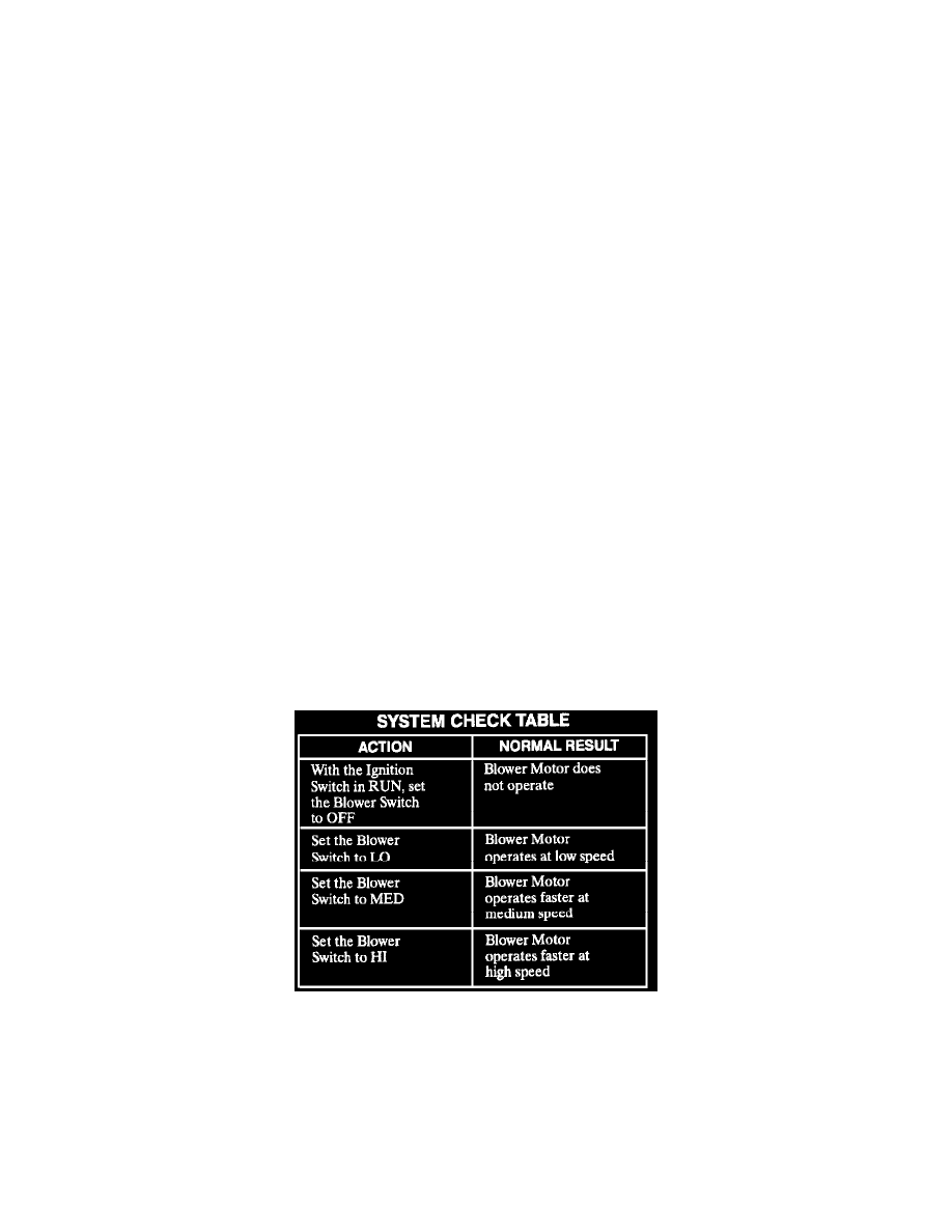
The Blower Motor delivers air to the interior of the vehicle. Its speed is controlled by the Blower Switch and the Blower Resistor Assembly. When the
Ignition Switch is in RUN, battery voltage is applied to the Blower Switch. With the Blower Switch in LO, voltage is applied across both Blower
Resistors and the Blower Motor; the Blower Motor runs at its slowest speed. With the Blower Switch in MED, one of the Blower Resistors is bypassed;
the Blower Motor runs faster. When the Blower Switch is set to HI, battery voltage is applied directly to the Blower Motor; the Blower Motor runs at its
fastest speed.
System Check
System Check Table
^
Use the System Check Table as a guide to normal operation.
^
Refer to System Diagnosis for a list of symptoms and diagnostic steps.
^
Refer to System Diagnosis when a result is not normal. See: Without Air Conditioning/System Diagnosis
System Diagnosis
^
Do the tests listed for your symptom in the Symptom Table. See: Symptom Related Diagnostic Procedures/Without Air Conditioning
^
Tests follow the Symptom Table.
^
If your symptom does not appear in the Symptom Table, perform all of the tests.