
J2000/Sunbird V6-191 3.1L VIN T MFI (1994)
Dashboard / Instrument Panel: Service and Repair
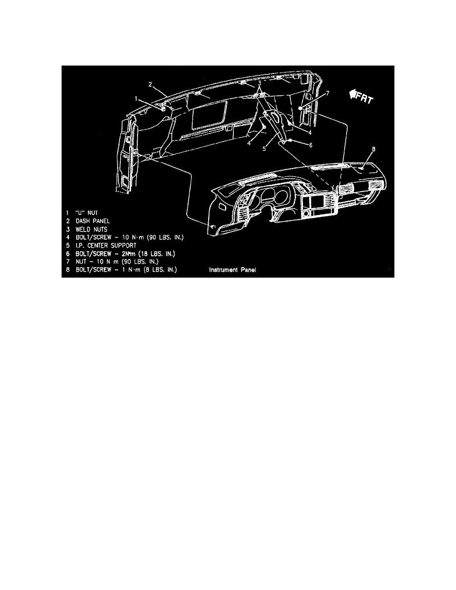
Instrument Panel Assembly
INSTRUMENT PANEL ASSEMBLY
REMOVE OR DISCONNECT
1. Negative battery cable.
2. Right and left sound insulators.
3. Steering column opening filler. See: Body and Frame/Interior Moulding / Trim/Trim Panel/Service and Repair/Steering Column Opening Filler
4. Right and left Instrument Panel (I/P) trim plates. See: Body and Frame/Interior Moulding / Trim/Trim Panel/Service and Repair/Instrument Panel
Trim Plates
5. Console housing. See: Body and Frame/Interior Moulding / Trim/Console/Service and Repair
6. Instrument panel compartment/door. See: Body and Frame/Interior Moulding / Trim/Glove Compartment/Service and Repair
7. Heater and AC control. See: Heating and Air Conditioning/Control Assembly/Service and Repair
8. Convenience center. See: Maintenance/Fuses and Circuit Breakers/Relay Box/Service and Repair
9. Forward lamp harness and engine harness connector from bulkhead.
10. Bulkhead from cowl. See: Bulkhead
11. Hood release handle, retained by 2 set screws.
12. Defroster grilles.
13. Four upper instrument panel retaining screws located in defroster duct openings.
14. Two lower corner instrument panel retaining nuts.
15. One screw to instrument panel brace at left side of Instrument Panel (I/P) compartment opening.
16. Two nuts securing wire harness to neutral start switch. (Manual Transmissions Only)
17. Three steering column retaining bolts: 2 at Instrument Panel (I/P) pad, 1 at cowl and lower steering column.
18. Pull instrument panel assembly out far enough to disconnect ignition switch, headlamp dimmer switch and turn signal switch. Disconnect all other
electrical wiring connectors, vacuum lines and radio antenna lead to remove instrument panel assembly.
19. Instrument panel assembly with wiring harness attached.
INSTALL OR CONNECT
1. Instrument Panel (I/P) to cowl.
2. All electrical connectors and vacuum hoses.
3. Three steering column retaining bolts.
4. Screw into instrument panel brace at left side of I/P compartment.
TIGHTEN
-
Screw to 7 Nm (57 lb in).
5. Two lower corner instrument panel retaining nuts.