
Lemans FWD L4-121 2.0L (1989)
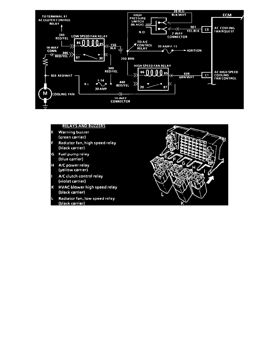
Wiring Diagram For Cooling Fan With A/C
Relay Component Location
CIRCUIT DESCRIPTION:
The radiator cooling fan will run on low speed any time the A/C compressor clutch is engaged. Battery voltage is applied to terminal "86" of the low
speed fan relay, through the A/C compressor clutch relay. This closes the relay and completes the circuit as follows: from the number 14 fuse, to circuit
440, to the relay, through circuit 340, to the .6 ohm resistor, and the fan motor. The high speed cooling fan relay is ECM controlled. The ECM will
ground circuit 939, which actuates the relay. Once this occurs, the high speed fan motor circuit completes as follows: from the number 14 fuse, to circuit
440, to the relay, through circuit 903, to the fan motor. The ECM will run the fan at high speed if the following sets of conditions are met.
Condition 1
a. Malfunction Codes 14 or 15 are present.
Condition 2
a. Engine coolant is greater than 107°C (224°F).
Condition 3
a. Engine coolant is between 26°C and 107°C (79°F and 224°F).
b. Vehicle speed is less than 44 mph.
c. High pressure blower switch closed.
TEST DESCRIPTION: The numbers below refer to circled numbers on the diagnostic chart.
1.
See the Relay Component Location above for relay identification.
2.
Since the low speed fan relay is energized by the voltage applied to the clutch, it is important to notice if the A/C clutch is energized in this step. If
the A/C clutch is inoperative, then it will be necessary to repair that circuit first using CHART C-10.
3.
With the ignition "ON" and the diagnostic terminal grounded, the ECM should be grounding circuit 939, and the test light should illuminate.