
Parisienne V8-305 5.0L (1985)
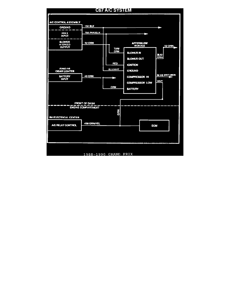
FIGURE 5 - CIRCUIT DIAGRAM
The following five (5) figures are current summaries of afterblow module circuit diagrams, for carlines covered by an A/C odor bulletin. They can be
used to either wire an affected vehicle, or they can serve as examples for wiring other systems not specifically, covered by an A/C odor bulletin.
Installation Precautions:
^
Disconnect the negative battery cable before performing any electrical hook-ups.
^
All the connections of the afterblow module harness to the vehicle wiring should be performed using the technique described in Section 8A of the
Service Manual. Splices/connections should be made using splice clips, or solder. Do not use instant connectors such as 3M's "Scotchblock"
brand, ^ All unused module wires must be taped and secured to prevent future electrical problems.
^
The afterblow module is not compatible with some non-factory installed theft alarm systems. The module current draw in the key off position
could trigger alarms that sense battery voltage changes or current drain.
Testing the Afterblow Module:
1.
Start the engine.
2.
Command the A/C system ON and ensure the compressor engages.
3.
Apply battery voltage to the green test lead (PIN H) for at least 30 seconds while the compressor is engaged.
4.
Turn ignition off.
5.
The blower should: come on after approximately 10 seconds; run for 1 second; then shut off.
6.
Disconnect the jumper wire.
Warranty Information:
Labor Operation:
T6235
Labor Time:
Refer to applicable bulletin.