
Solstice L4-2.0L Turbo (2008)
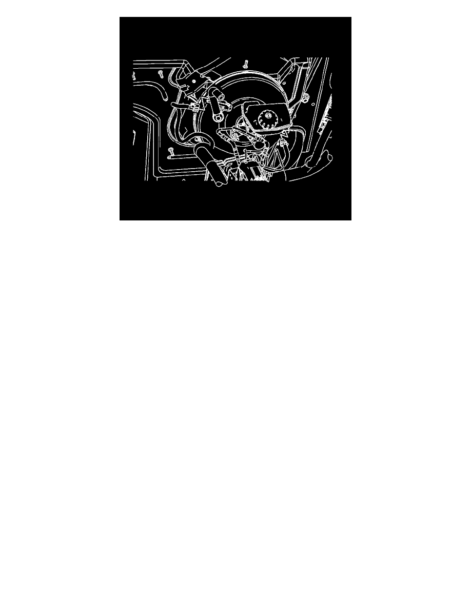
15. Connect the brake booster vacuum sensor electrical connector.
16. Connect the brake fluid level indicator switch electrical connector.
17. If a new brake modulator assembly was installed, program the brake modulator assembly. Refer to Electronic Brake Control Module Programming
and Setup (See: Testing and Inspection/Programming and Relearning) .
Important: A new brake modulator assembly comes with both the primary and secondary circuits pre-filled with brake fluid. If the
ignition key has not been cycled after installation, only a base brake bleed is necessary.
18. Bleed the hydraulic brake system. Refer to Hydraulic Brake System Bleeding (Manual) (See: Brake Bleeding/Service and Repair)Hydraulic Brake
System Bleeding (Pressure) (See: Brake Bleeding/Service and Repair) .
19. Perform the Diagnostic System Check - Vehicle (See: Testing and Inspection/Initial Inspection and Diagnostic Overview/Diagnostic System
Check - Vehicle) .
20. Observe the brake pedal feel after performing the diagnostic system check. If the pedal now feels spongy, air may have been introduced into the
secondary hydraulic circuit of the brake modulator which then may have been introduced into the primary circuit. If the pedal feels spongy,
perform the Antilock Brake System Automated Bleed Procedure (See: Brake Bleeding/Service and Repair) .