
Sunfire L4-138 2.3L DOHC VIN D MFI (1995)
10.
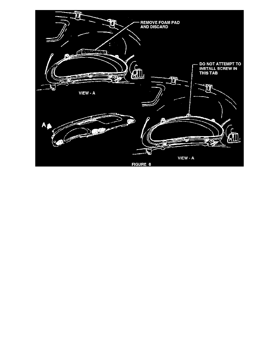
Remove I/P cluster trim plate/bezel from rear of topper pad five 7mm hex (or T15 torx) screws. See figure 6.
11.
Install new I/P cluster trim plate/bezel to rear of topper pad with five 7 mm hex (or T15 torx) screws, using the same fastener locations utilized on
old trim plate/bezel.
[Do not attempt to install a screw in the center upper screw position.]
Tighten screws to 2.3 Nm (1.7 Lbs.Ft. or 20 Lbs.in.). OR Screws are to be fully driven, seated, but not stripped. See figure 6.
IMPORTANT:
MAKE SURE THAT FOAM PADDING (GRAY @ 1" THICK) HAS BEEN REMOVED FROM UNDERSIDE OF TOPPER PAD ABOVE I/P
CLUSTER TRIM PLATE/BEZEL. FAILURE TO REMOVE THIS PADDING MAY RESULT IN REPEATED SAGGING OF THE CLUSTER
TRIM PLATE/BEZEL.
12.
Carefully position topper pad to I/P.
13.
Install four 7 mm hex (or T15 torx) screws (black) to upper forward edge of topper pad. Tighten screws to 2.3 Nm (1.7 Lbs.Ft. or 20 Lbs.In.). OR
Screws are to be fully driven, seated, but not stripped. See figure 5.
14.
Install four 7 mm hex (or T15 torx) screws (black) to lower rear edge of topper pad. Tighten screws to 2.3 Nm (1.7 Lbs.Ft. or 20 Lbs.In.). OR
Screws are to be fully driven, seated, but not stripped. See figure 5.
15.
Install two 7 mm hex screws (gold/brass colored) to topper pad at forward edge of SIR panel. Tighten screws to 2.3 Nm (1.7 Lbs.Ft. or 20
Lbs.In.). Or Screws are to be fully driven, seated, but not stripped. See figure 5.
IMPORTANT:
THE GOLD/BRASS COLORED SCREWS MUST BE INSTALLED INTO THEIR ORIGINAL LOCATIONS AT THE FORWARD EDGE OF
THE SIR PANEL.
SOME VEHICLES (A VERY SMALL NUMBER) MAY HAVE THREE FASTENER LOCATIONS AT THE FORWARD EDGE OF THE SIR
PANEL. ON THESE VEHICLES, THE FASTENERS MUST BE INSTALLED IN THE TWO LOCATIONS CLOSEST TO THE LEFT
(DRIVER'S) SIDE OF THE SIR PANEL.
16.
Install glove box trim plate using three Phillips head screws. Tighten screws to 2.3 Nm (1.7 Lbs.Ft. or 20 Lbs. In.). OR Screws are to be fully