
Sunfire L4-2.2L VIN 4 (1996)
Service of the PCM should normally consist of either replacement of the PCM, EEPROM re-programming or a KS module change.
If the diagnostic procedures call for the PCM to be replaced, the PCM should be checked first to see if it is the correct part. If it is, remove the KS
module from the faulty PCM and install it in the new service PCM. The service PCM will not contain a KS module. DTC P0601 indicates the EEPROM
programming has malfunctioned. When DTC P0601 is obtained, re-program the EEPROM. If a DTC P0325 is set, check the KS module for proper
installation. If it is installed correctly and DTC P0325 is still displayed, replace the KS module.
When replacing the production PCM with a service PCM (controller), it is important to transfer the broadcast code and production PCM number to the
service PCM label. DO NOT record on PCM cover. This will allow positive identification of PCM parts throughout the service life of the vehicle.
CAUTION: In order to prevent internal damage to the PCM, the ignition must be OFF when disconnecting or reconnecting the PCM connector.
The ignition should be OFF for at least 10 seconds before disconnecting power to the PCM so the IAC valve has time to move to the engine OFF
position.
REMOVAL PROCEDURE
1. Disconnect the negative battery cable.
2. Remove the RH engine splash shield.
3. Remove the horn attaching bolt.
4. Disconnect the horn electrical connector and horn.
5. Remove the PCM retainer attaching bolts.
6. Slide the PCM (4) and retainer from PCM bracket (2).
7. Disconnect the PCM electrical connectors (3).
8. Remove the retainer from PCM.
CAUTION:
-
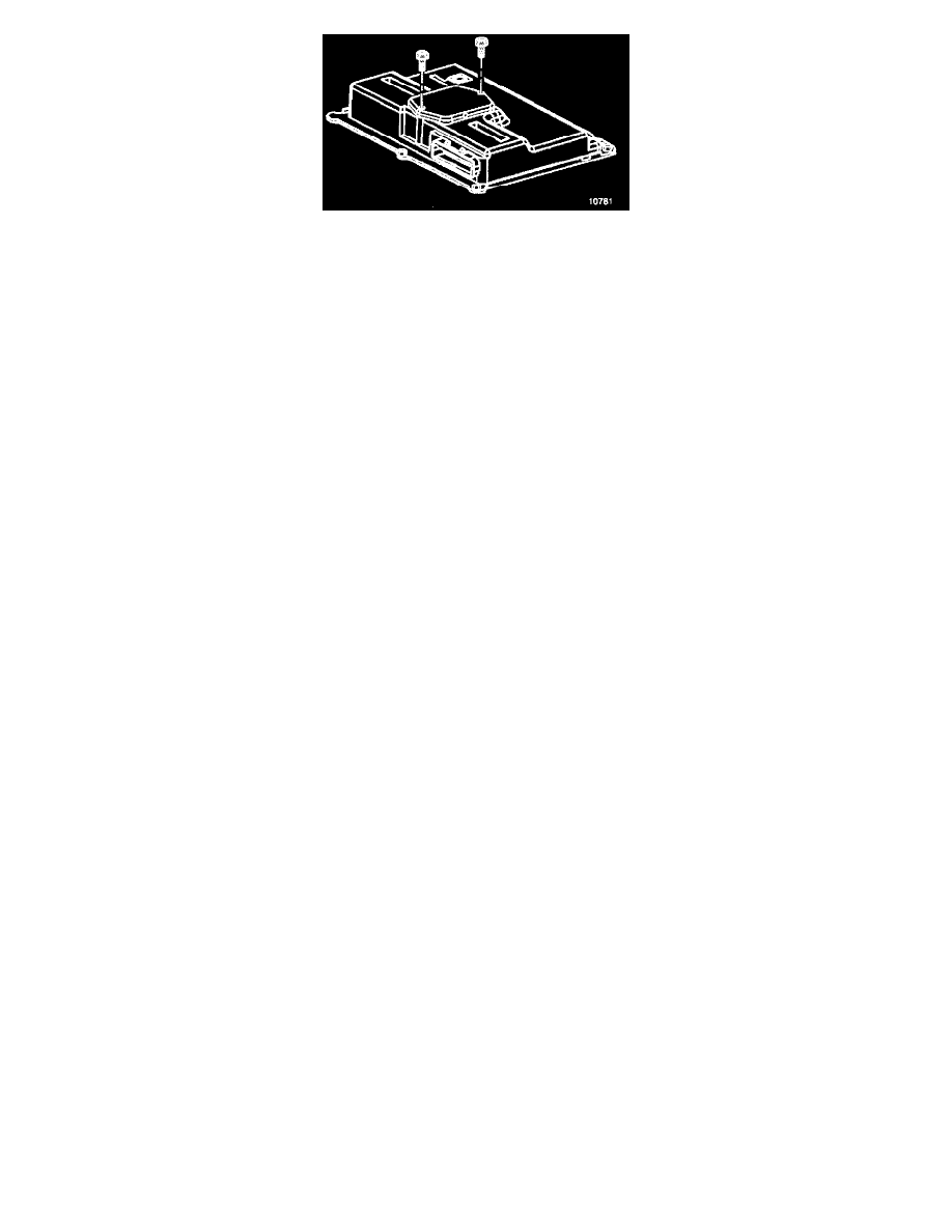
Before removing KS module cover, carefully clean PCM housing of any debris that may cause damage to PCM circuitry.
-
To prevent possible Electrostatic Discharge damage to the PCM or KS module, DO NOT touch the connector pins or soldered components on
the circuit board and DO NOT remove the integrated circuit boards from the carrier.
9. Remove the KS module cover.
10. Remove the KS module.
INSTALLATION PROCEDURE
Refer to the Latest Techline Information on Re-Programming or Flashing procedures.
1. Install the KS module in KS module socket.
2. Install the KS module cover.
3. Slide the PCM (4) into PCM retainer.
4. Connect the PCM electrical connectors (3).
5. Slide the PCM retainer into PCM bracket (2) slots.
6. Install the PCM retainer attaching bolts.
Tighten
Bolts to 8-12 Nm (69 lb. ft.).
7. Connect the horn electrical connector and horn.
8. Install the horn attaching bolt.
9. Install the RH engine splash shield.
10. Connect the negative battery cable.